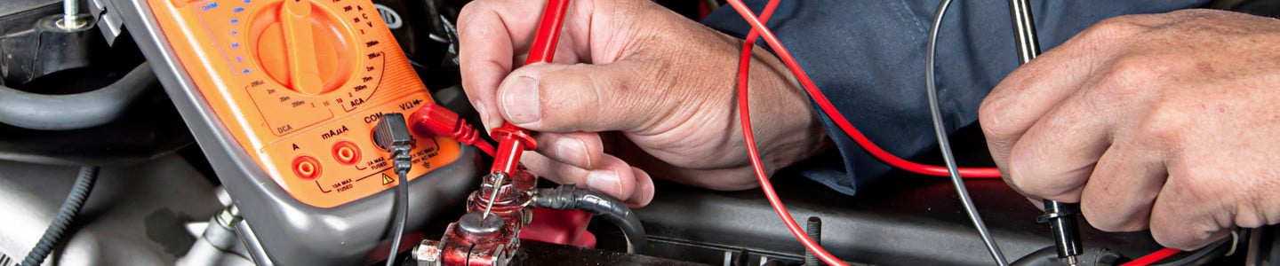
The digital multimeter (DMM) is an extremely versatile tool for troubleshooting electrical systems and diagnosing engine performance – combining the functions of many electrical measuring devices into one. Digital multimeters can measure voltage, electrical resistance, continuity, current, or test diodes in either direct current (DC) or alternating current (AC) with just a turn of a knob. They have the capability to make precise measurements out to 2, 3, 4, or more decimal places.
In automotive applications, they can test the degree to which fuses, wires, switches, relays, motors, and other automotive electrical parts are conducting electricity properly. Top-of-the-line DMM's are also able to read engine rpms and dwell as well as electrical duty cycle, frequency, pulse width, diode condition, and in some cases, temperature. In this article, we'll cover the basic functions of a multimeter, the symbols they use, how to do basic tests, and compare features found on a few different DMMs ranging in price from about $25.00 to just over $50.00.
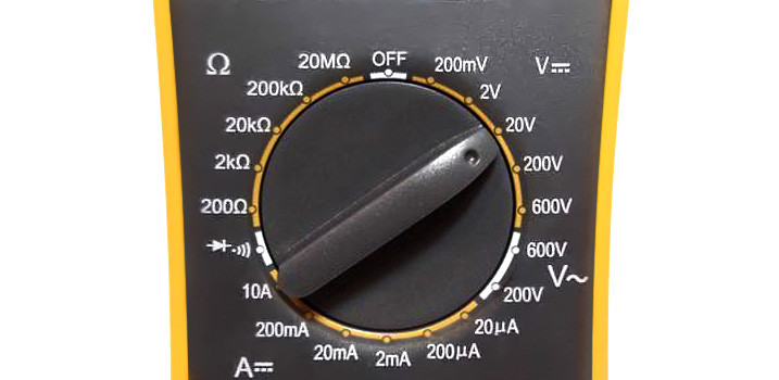
Before DMMs, technicians relied on analog meters which used a rather imprecise needle gauge. DMM's provide a digital readout which is many times more accurate than an analog reading. Most DMM's have a dial that allow the user to select what is being measured (volts, amps, resistance, etc.), and more importantly, allow the user to select the "range" of measurement. Simply put, "range" is defined as the highest value that the multimeter will record with the dial in that position.
For example, when measuring volts, a DMM may allow the user to set the dial at 2V, 20V, 200V, or 600V. If the user knows the approximate expected value, the range closest to that should be selected for the most accurate result. More about this later on in this article when we discuss common uses. Once a test range has been chosen, positive (red) and negative (black) leads are connected to the circuit in the same way as individual (non-multi) meters would be.
Understanding Multimeter Readouts
Since DMMs may display very large or small numbers, symbols will be used to clue the user if a number displayed (5, for example) should be multiplied or divided by a certain factor.
Exponential prefix symbols used are:
- M (Mega) = 1,000,000 (used for ohms readings)
- K (Kilo) = 1,000 (used for ohms readings)
- m (Milli) = .001 or 1/1,000th (used for amp and volt readings)
- µ (Micro) = .000001 (1/1-millionth)
- n (Nano) = .000000001
- p (Pico) = .00000000001
Additionally, users should be familiar with the following:
- V = Refers to voltage, or the amount of electromotive pressure
- ? = The Greek alphabet symbol for Omega is used for ohms, or electrical resistance
- A = Refers to amperes, or current flow
Top Uses For Multimeters
While modern multimeters can perform dozens of functions, we will cover four of the more common automotive tests you might want to run: voltage, continuity, amperage, and diode testing.
1. Measuring Voltage (V)
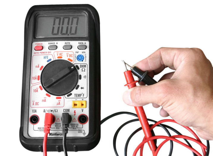
If your DMM measures both AC voltage and DC voltage, you want to choose DC for automotive applications. The vast majority of cars on the road today use 12V DC systems, so if there is a choice of ranges, choose the one closest to, but above, your expected readings. In the photo above, the appropriate range of 20V is chosen. Insert the test leads into the DMM: the black lead should be plugged into "COM" for common, and the red lead should be plugged into the terminal which indicates "V".
Voltage is checked via a parallel connection, so do not disconnect the device you are testing. Touch the red lead to the positive side of the device, and the black lead to the negative side of the device (or to a good known ground). The result will appear on the screen. If there is a negative sign in front of the reading, reverse the terminals.
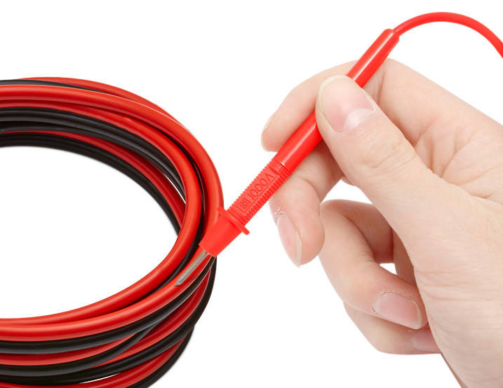
Note! When testing an insulated wire, use the very sharp tip of the probe to pierce the plastic wire sheathing. The probe tip must touch copper to get an accurate reading.
Examples of voltage tests:
- Red lead to battery positive and black lead to battery negative will provide battery voltage (with engine off, a good battery should read between 12.6V and 13.2V).
- With headlights "on", red lead to a wire in a wire harness and black lead to a good known ground will confirm a wire has voltage, or is "hot". This is helpful if searching for such a wire when installing a new headlight assembly.
Charging System Test:
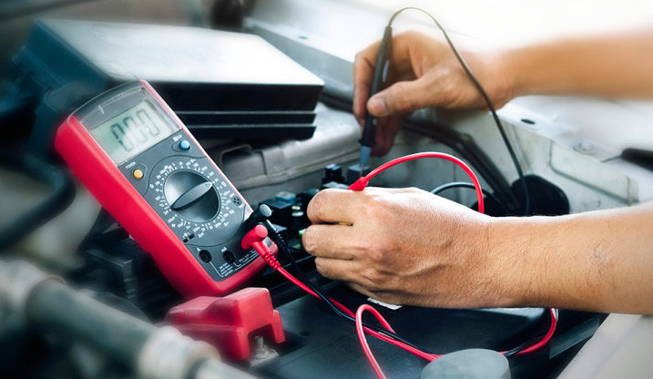
First, check the battery itself with the engine off as described above. If the battery is healthy, start the engine and monitor the voltage with the leads still on the battery posts. With all accessories off, optimal voltage of a properly functioning alternator ranges from 13.7 to 14.9 volts. A low voltage reading at this point signifies a problem with the alternator or the wiring between the alternator and the battery. A high voltage reading of 16 or more volts signifies the alternator or voltage regulator is defective and overcharging the battery.
2. Measuring Continuity (?)
If you're checking to see if a fuse is good, or if there's a break ("open" in electrical terms) in a wire harness, you are checking for continuity between one end of the device, wire or circuit and the other. Note! This test MUST be done with NO electrical current flowing through the circuit! If necessary, remove the device from the car or disconnect the vehicle's battery to ensure this.
Depending on the DMM, there may be a "continuity" dial setting, or you may need to choose "ohms/resistance". The black test lead is inserted into COM, and the red test lead is inserted in the "Omega" or "resistance" connection (check the multimeter's user manual).
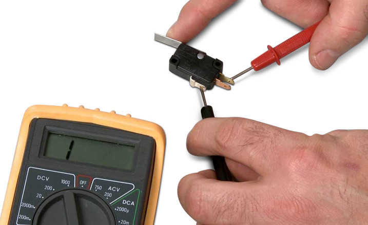
Touch the two leads to either end of the device, fuse, or wire you are testing. A reading of infinity, or "1", or "OL" (again, check the instructions for your specific meter) means that the circuit is open and cannot conduct electricity, while a reading of "zero" or close to zero means the circuit is complete and can conduct electricity. Some DMM's emit a tone when continuity is good.
To test if a switch is faulty, touch the tester leads to both poles on the switch. Turning the switch being tested from "off" to "on" should change the multimeter's reading from infinity to zero if the switch is working properly. If you're checking an electrical motor in this fashion, a reading slightly above zero confirms enough continuity exists within the motor for current to pass through easily.
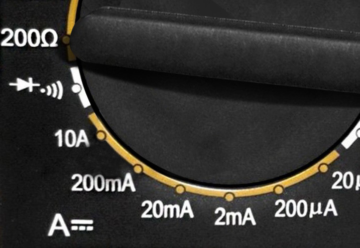
3. Measuring Amperage (A)
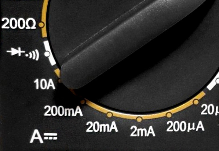
Set the DMM dial to "A" for amps or current. Best choices to use for range are either 10amps if dealing with a higher amount of current, or 300 milliamps (mA) if you'll be tracking lower amounts of electrical flow.
Note! Unlike voltage and resistance testing, amperage testing is done "in series", meaning one end of the device must be disconnected from the circuit. The meter leads will be connected between the device and the disconnected wire or terminal, and in that way, the DMM completes the circuit.
Insert the test leads into the multimeter: black to "COM", and red to "A" or "mA". Touch positive and negative leads to corresponding sides of the disconnected circuit. Current will flow first into the circuit, through the red lead, through the multimeter, and back to the circuit through the black lead. At this point, you'll get an amperage reading on the display.
4. Testing Diodes
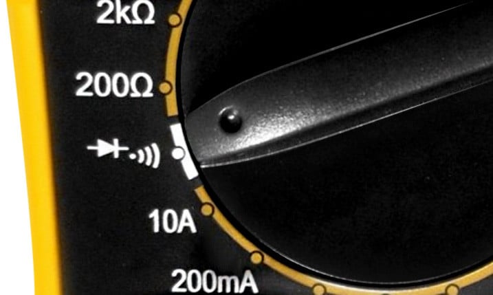
A diode is a component that allows current to flow in one direction, but not the other. Testing diodes involves running current through the diode in both directions. If your DMM is capable of testing diodes, turn your multimeter's dial to the diode test setting, usually marked by a symbol showing an arrow pointing at a vertical line (as in the above photo). The black lead should be inserted into COM, and the red lead into the terminal marked for measuring volts, ohms, or diodes.
Note! Before testing, a diode must be disconnected from its circuit!
Test forward bias first by touching the red lead to the positive side of the diode and the black lead to the negative side. Readings greater than zero but less than 1 indicate good forward bias.
To test reverse bias, switch the red and black probes to the opposite sides of the diode and look for a reading of "1", "infinity", or "OL" (overload) to signify reverse bias is good. (Check your user's manual for the specific reading you should see.) If you get the same readings in both tests, whether zero or "OL", then the diode is bad.
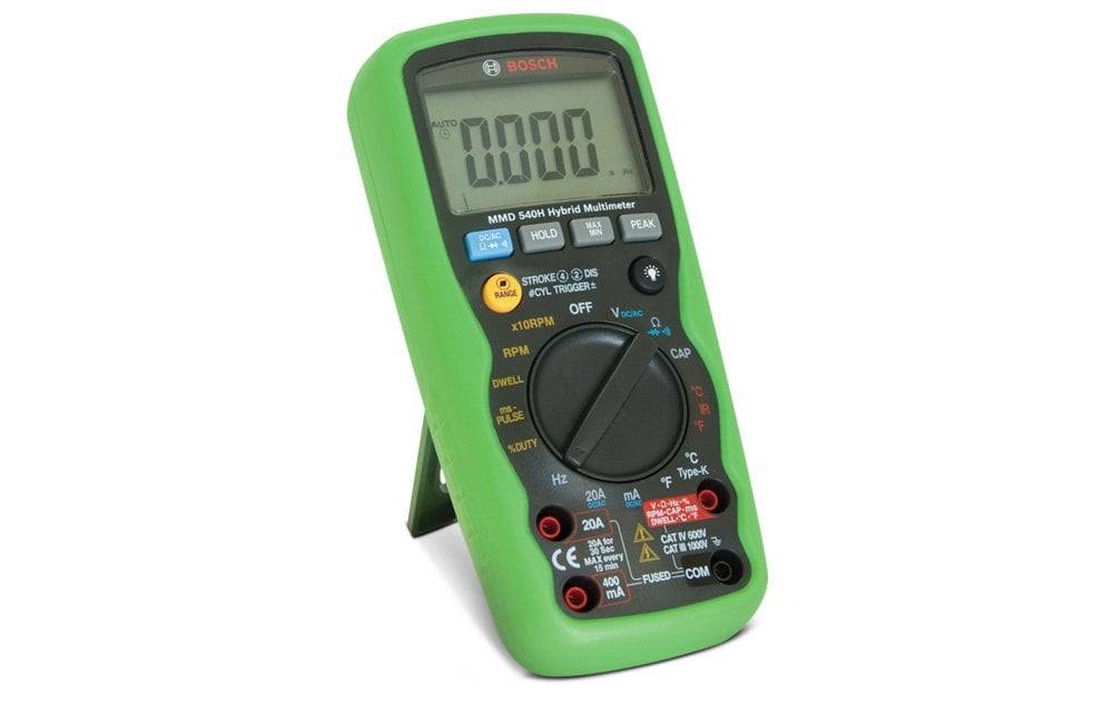
A Brief Comparison Of Three Multimeters
To give you an idea how multimeters can vary, let's take a look at three offerings at different price levels from one manufacturer.
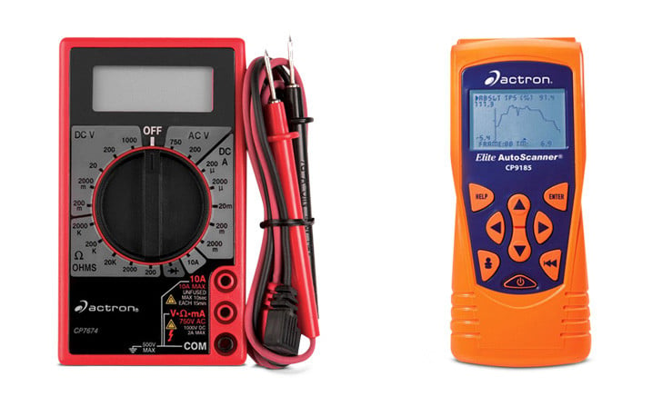
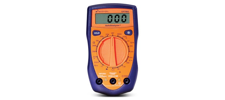
Actron Digital Multitester
This digital multimeter includes the functions of an ammeter, voltmeter, and ohmmeter as well as the ability to measure AC voltage. It can also test diodes and transistors. It has 19 ranges, a detachable set of leads, automatic polarity sensing, and automatic zero adjustment. This is a good multimeter for basic electrical testing, usable at home as well as on vehicles.
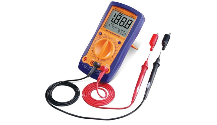
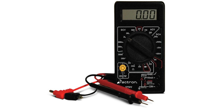
Compared to the previous model, this DMM offers extended ranges for DC volts and OHMS, and has dial settings for testing 1.5V and 9V batteries. A "hold" button allows the user to hold readouts. A folding stand and alligator clips are also included.
This is a full-service digital multimeter with 24 ranges compared to 19 for the previous two models. Additional automotive benefits include the ability to test engine rpm and dwell. There is a separate dial selection for continuity, as well an audible tone.
Whether you choose one of these highlighted Actron models, or another digital multimeter from our vast selection of tools, these devices make it simple to conduct basic electrical tests on your vehicle. By doing this work yourself, you can save time and money, and be more knowledgeable about the inner workings of your ride.