
frequently asked questions
- Should I use any type of sealant when installing this gasket?
-
- No, Fel-Pro gaskets are designed to be installed on a clean and dry surface.
- Why are MLS Head Gaskets being used in late model applications?
-
- Multi-Layer Steel is the latest development in head gasket technology. The three to five layers of stainless steel shims provide the ultimate in torque retention and supplies extra strength to support current lightweight aluminum casting designs.
- What are Torque-to-Yield Head Bolts?
-
- Torque-to-Yield Head Bolts are tightened to their yield point by tightening the bolts to a specified torque and then tightening them an additional partial turn. This creates a more even clamping force over the entire area of the gasket.
- Can Torque-to-Yield Head Bolts be reused?
-
- The Torque-to-Yield procedure permanently stretches the bolts into their elastic range approaching the bolts elastic limit. Reusing these bolts will likely result in either head gasket failure due to a false torque reading or the bolts may break.
- This gasket can be installed with either side facing up, how can I tell which way to install this head gasket?
-
- FEL-PRO head gaskets have directional markings of either front, left, right, top or up to help install them correctly when the orientation is critical.
- What Is Cylinder Head Lift?
-

- Cylinder head lift is a phenomenon that occurs when the cylinder pressure in an internal combustion engine causes the head to lift away from the deck surface of the engine. In minor cases, this can result in combustion gasses entering coolant passages. This pressurizes the cooling system and pushes coolant out of the cooling system, which will lead to overheating. In more severe cases, head gasket damage can occur, leading to head gasket failure.
- The illustration here depicts a cylinder head that is lifting during the combustion cycle. The red area above the head gasket is the gap created by the lifting. This gap fills with hot combustion gasses and the corrosive air-fuel mixture. Cylinder head lift is caused by excessive cylinder pressure, which can result from several things, including detonation and/or pre-ignition; improper fuel type; over-advanced ignition timing; improper air-fuel ratio; vacuum leaks; malfunctioning sensors; and increased boost pressure.
- Detonation, also known as knock, is one of the most common. During normal combustion, the spark from the spark plug ignites the air-fuel mixture, which leads to a controlled burn and normal cylinder pressures. When knock occurs, another flame front occurs outside of the spark-induced flame front, causing uneven burn and creating shock waves. Cylinder pressures spike when this happens, exceeding the pressures the cylinders and head gasket were designed to hold.
- Over-advanced ignition timing can also cause knock. Modern engines have electronically controlled timing systems that can reduce timing advance if knock is detected. If the wrong grade of fuel is used and the vehicle’s computer does not adequately adjust the ignition timing, knock can still occur, and cylinder pressure will still spike.
- High compression ratios and forced induction (by the means of supercharging or turbocharging) are ways to increase either performance or fuel economy. Unfortunately, head lift is a common problem for these applications too. When air is compressed, it heats up. Hotter air entering the cylinder increases the likelihood of detonation. Cylinder pressures are also greatly increased when boost pressure is increased to make more power, even if detonation is not occurring.
- What's That Leak Under My Car?
-
- As you are pulling out of the garage this morning, you notice a spot of liquid on the ground. Your heart drops… what is leaking from your car and where is it coming from?
- To get a better idea of what is going on with your car, you can put a piece of white cardboard under your car to identify the color of the leak and where it is coming from. Then you can compare what you find with the chart below to get a handle on the situation. Be sure to consult your owners manual if you have any questions regarding the fluids in your vehicle.

BROWN
- Brown fluid leaking from your vehicle is likely motor oil. Newer motor oil will be light brown while older oil is dark brown. An oil leak can be traced to a worn gasket or seal, an oil plug that isn’t properly secured, high oil pressure or an oil filter that isn’t put on properly.

RED
- Red fluid can indicate that the transmission or power steering system is leaking. Transmission leaks will appear near the front or middle of the vehicle while power steering leaks will be toward the front.

ORANGE
- Orange or amber fluid can indicate a leak of extended-life coolant. Coolant leaks can occur from a worn gasket on the engine, from the radiator or from heater and radiator hoses and engine core plugs.

YELLOW
- Yellow liquid is likely a leak of radiator coolant. Coolant leaks can occur from a worn gasket on the engine, from the radiator or from heater and radiator hoses and engine core plugs.

GREEN
- Green liquid points to an antifreeze (coolant) leak. Antifreeze leaks can occur from a worn gasket on the engine, from the radiator or from heater and radiator hoses and engine core plugs. Clean up leaks promptly, antifreeze is poisonous and dangerous to your pets because it has a sweet smell and taste.

BLUE
- If you notice blue liquid coming from your vehicle, it likely is windshield wiper fluid. Inspect the tubes leading from the wiper fluid reservoir for leaks.

CLEAR
- If on a hot day you see water coming from your vehicle, don’t worry it’s just condensation from your air conditioning system.
- What Causes Oil To Leak?
-
PREVENTING OIL LEAKS
- Your vehicle’s engine relies on motor oil that is recirculated throughout the engine to keep everything running smooth. If any of the oil leaks out, it can lead to engine damage. Preventing the oil from leaking out is a variety of gaskets and seals. Simply put, gaskets are your engine’s last line of defense for preventing leaks.
- If you discover oil spots in your garage or driveway, it needs to be investigated to determine if a gasket or seal has failed and is no longer doing its job. Read on to learn why gaskets and seals can develop leaks and which gaskets are most susceptible to leaking oil.
WHY DO GASKETS LEAK?
- Gaskets are required to do their jobs inside of your engine, which is a pretty hostile place to work. Constant exposure to high temperatures, high pressures, vibrations and contact with hot fluids over a period of time will cause even the best gasket or seal to develop leaks. Except for very rare cases of catastrophic failure, gasket leaks start out as small drips that you may first notice as spots under your car. These may lead to unsightly stains that appear on your parking spot and eventually become more prevalent if not taken care of.
- There is a natural tendency to dismiss the importance of small leaks of oil and put them on the list of things to fix later – but resist putting it off. Even small leaks can mean big expenses down the road if they are ignored. What starts out as a relatively easy fix can quickly turn into a major issue. Even a small leak can cause you to lose a quart of oil in no time.
LOW OIL LEVELS CAN CAUSE ENGINE PROBLEMS
- Car-Oil-Dipstick
- Driving with low or no oil is a recipe for expensive repair bills. Many drivers dont realize that driving with low oil level can cause high engine temperatures. Higher engine temperatures will break down the lubrication ability of the remaining oil, causing damage to and excess wear of pistons, piston rings, valve lifters and engine bearings. The high engine temperatures may exacerbate the leakage of the gasket, creating a spiraling series of events that will impact your wallet with a hefty repair bill.
COMMON SOURCE OF OIL LEAKS: VALVE COVER GASKET
- The best place to start tracking down the source of an oil leak is with the valve cover gasket, perhaps the most common source of engine oil leaks. Valve covers are typically made of lightweight aluminum, or magnesium, plastic composite or stamped steel and may warp over time, so the surface that mates with the cylinder head is no longer flat, creating oil leaks. In addition, the lightweight material can be deformed by excessive torque on the fasteners holding it in place.
- If there is no structural issue with your valve cover, the gaskets may take a compression set where they no longer can provide proper sealing. The gasket will lose some of its elasticity over time and does not maintain its’ original sealing ability.
- If there is an overabundance of dirt around the valve covers, use some degreaser and some rags to clean the area so you can see bare metal near the valve cover/cylinder head joint. Check the area after running the engine for a bit and you’ll be able to see if the valve cover gasket is leaking. If this area is leaking, we recommend against trying to tighten the cover’s fasteners. Overtightening may distort the valve cover and gasket, making the leak worse. Many covers of today have load stops built into them so tightening the cover will not help.
- If the valve cover gasket is not the source of your oil leak, the following gaskets or seals may be likely sources:
- Oil drain plug seal
- Oil pan gasket
- Front and rear crankshaft seals
- Camshaft seals – overhead cam engines
- Timing cover gasket
- Intake manifold end seals
- Cylinder head gasket
- Oil filter adapter/oil cooler base gaskets
FINAL THOUGHTS
- If you are experiencing an oil leak, consult your professional technician. They’ll be able to not only diagnose the problem but complete the necessary repairs. Before you know it, your garage will be free of those dreaded oil stains.
- Learn more about Fel-Pro quality gaskets that are specifically designed for the repair environment, find your car part, or find where to buy your auto part today.
- Which Direction Should You Install A Fel-Pro Gasket?
-
- Installing gaskets in the correct direction is critical. In this article, Fel-Pro® will help you determine ‘which side is up’ to correctly install various gaskets types.
- Some gaskets are asymmetric, and the correct orientation can be visually distinguished. However, others can be installed with either side facing up and the gasket will seal either way. Sometimes gaskets for the same engine might appear very similar, but will not function properly if installed in the wrong direction.
GETTING ORIENTED
- So how do you know which way a Fel-Pro gasket is supposed to face when it’s being installed? Fortunately, in the case of head gaskets and intake manifold gaskets, most Fel-Pro gaskets have directional markings to help install them correctly when gasket orientation is critical to the installation.
- Before we take a look at the different markings you’ll find on Fel-Pro gaskets, let’s talk about what we mean when we say front, left, right, top and up. Different nameplates use different nomenclature in their OE service manuals for directional markings; for consistency in leveraging repair information, Fel-Pro works to follow the nameplate reference.

FRONT
- What is the FRONT of the engine? This can be confusing, especially when dealing with a transversely-mounted engine, which most front wheel drive vehicles have. The answer is quite simple though – the front of the engine is the end where the drive belts are located.

RIGHT AND LEFT
- RIGHT and LEFT are determined from the driver’s perspective – the industry standard. If you were to install your gaskets on the left and right side based on looking at the engine from the front of the vehicle, the gaskets would be incorrectly installed.

TOP OR THIS SIDE UP
- TOP or THIS SIDE UP means that’s the side of the gasket that should be facing you once it’s installed.

UP
- The UP stamp is found on Fel-Pro head gaskets for Subaru engines, which have horizontally opposed cylinders. The edge of the gasket with the Up stamp must be kept up toward the top of the engine block.
- How to Prepare an Engine Surface for Gasket Installation
-
PREP WORK REQUIRED
- The engine’s most dynamic and critical seal, the head gasket must withstand high temperatures and casting movement to create a perfect and reliable seal. It not only must contain the extreme cylinder pressures generated during the combustion process, but also has to seal high pressure oil and the oil drain backs, and engine coolant. There are a number of variables that contribute to both the horizontal and vertical motion that occurs between the cylinder head and engine block (deck area).
- Fel-Pro uses a variety of the latest sealing technologies available to design head gaskets that conform and compensate for minor surface imperfections while being dense enough to maintain even loading between the cylinder head and block. However, even the best head gasket can’t seal a surface that is improperly prepared. Before installing a new head gasket, surface conditions of the engine block and cylinder head must be inspected and refinished if they are out of spec.
DETERMINING THE PROPER FINISH
- Measuring-Surface-Finish-Profilometer
- In order to determine an appropriate surface finish, consider the metallurgy of the head and block castings as well as the material and design of the head gasket being used in the install. Different gaskets require different surface finishes, so the surface finish must be matched to the type of gasket that is required for the application. To determine surface finish requirements, consult the OEM repair manual.
- The importance of attaining the appropriate surface finish, one that matches the style of head gasket being used, cannot be overstated. Each type of Fel-Pro head gasket – whether it be PermaTorque® MLS, PermaTorque, solid or perforated core, single layer embossed steel, or other types – all require specific surface finish requirements. If the surface is too smooth, the gasket will have less "grip" and may leak; if the surface is too rough, the gasket will have a difficult time conforming to surface imperfections and may also leak. Surface finish can be checked using a surface finish comparator or a profilometer. Checking the cylinder head surface finish and flatness is an important step to take before installing a head gasket.
- How to Install Torque-to-Yield (T-T-Y) Bolts
-
BOLT BASICS
- Bolts are elastic by nature, meaning that within their elastic range, theyll stretch as the load on the bolt increases. As long as the bolt is not stressed beyond its proof load (the maximum load a bolt can withstand and still behave in an elastic manner), it will return to its original length once the torque is relieved. However, conventional bolts can be an issue when they are used on aluminum heads, given that the expansion rate of this type of head can stretch typical bolts past their yield point. This can be overcome by designing and offering better fasteners to address these conditions.
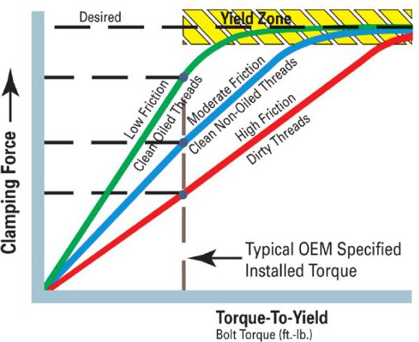
- Traditionally, a torque specification is a calculated number. This torque specification applies the proper clamp load to the joint while accounting for friction provided by the threads and the underside of the bolt head. Today’s engines require higher clamping forces (due to increased combustion pressure) which cannot be achieved with conventional small diameter bolts normally found in these engines. Unfortunately, using a larger diameter bolt is not the answer, as the larger a bolt it is, the less it will stretch. Remember, bolt stretch is how we get maximum clamping load.
TORQUE-TO-YIELD BOLTS
- Used by many manufacturers, especially on engines with aluminum heads and in conjunction with Multi-Layer Steel (MLS) head gaskets, T-T-Y (Torque-To-Yield) head bolts are engineered to stretch within a controlled yield zone. Once they reach this zone, they maintain a more precise and consistent level of clamping force across the entire head-to-block mating surface. The bolts are stretched into their elastic range, and in many cases, the stretching approaches the bolts elastic limit, permanently stretching it.
- Getting to the precise yield zone (for maximum clamping force) is accomplished by tightening bolts to a certain torque spec, then turning the bolts a pre-determined number of degrees. Rotating the bolts a set amount of degrees and putting the fasteners in the yield zone will account for “clamp load scatter” or variations due to conditions such as assembly lubricant type, bolt and bolt hole thread condition, and surface finish of the fasteners.
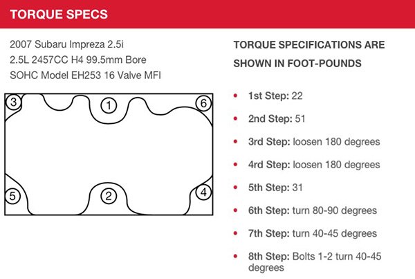
- For example – on the Subaru EJ253 2.5L naturally aspirated engine, a torque specification for a single bolt is to tighten to 22 ft./lbs., then 51 ft./lbs., loosen 180 degrees, then loosen another 180 degrees, torque to 31 ft./lbs., turn an additional 80-90 degrees, all bolts another 40-45 degrees, and finally the center bolts another 40-45 degrees.
- When T-T-Y bolts are rotated to their final number of degrees of rotation, T-T-Y bolts can approach their elastic limit and become permanently stretched. If removed and reused, it is likely that either the head gasket will fail (due to low clamp load) or the bolts will break.
- Fel-Pro offers replacement head bolts for T-T-Y that are application-specific. You should always replace the T-T-Y bolts; these bolts are designed to stretch, and reusing them will cause improper, uneven torque and clamping force. Stretched bolts can yield in the threaded portion or the shank portion. Yielded bolt threads can damage threads in the engine, especially on aluminum blocks, and since the bolts are weakened, they may break if retorqued.
- What are The Different Gaskets in My Engine?
-

- Gaskets are designed to provide a seal between two engine surfaces. Engines, by virtue of their material and function, are subject to changes in temperature and pressure while engine parts are subject to movement. As the engine heats up and cools down, it experiences pressure from compression and vacuum, and engine parts expand, contract, move away from each other and are drawn tighter.
- Because the engine experiences forces and stress from every direction, the gaskets are heated, cooled and rubbed. A cold gasket reacts differently than a hot gasket, just as a gasket under increased pressure acts differently under decreased pressure. Read on as we take a look at the different gaskets in your vehicle.

VALVE COVER GASKET
- Fel-Pro-Valve-Cover-Gasket
- The valve cover gasket sits between a relatively thin steel cover, cast aluminum or plastic composite cover and a cylinder head that is cast from iron, aluminum or alloy (mixture of metals or metals and non-metals). When the engine is first started on a cold day, the oil that flows through the system could be 32°F or colder. The gasket, like the head and valve cover, are just as cold. As the engine warms up, the oil, head, cover and gasket warm at different rates.
- The heat generated by the friction in the head and engine block heats the oil. As a result, the heat radiated by the block, head and oil heats the valve cover. Over many miles, time and engine heating/cooling cycles, the valve cover gaskets may no longer do their job of sealing and allow oil to leak out.

OIL PAN GASKET
- Oil-Pan-Gasket
- The oil pan gasket sits below the engine block in the area called the crankcase, named so because that is where the crankshaft resides. It is compressed between the crankcase and a durable steel pan or cast pan. The pan is relatively thinner than the crankcase, which is generally cast from iron, aluminum or alloy. The same physical aspects that affect the valve cover gasket and head gasket affect the oil pan gasket.
- Oil resides in the oil pan when an engine is not running and to return to while running. As the engine heats up on a cold winter day, the oil, pan and gasket follow suit. When the engine is turned off and the hot oil returns to the pan, the three cool at different rates. Over time, a stressed oil pan gasket can fail at different times, either under the cold condition, the warm condition or under the moving conditions of the pan against the case.

INTAKE MANIFOLD GASKET
- Fel-Pro-Intake-Manifold-Gasket
- Intake gaskets can be made from aluminized steel coated in a carbon-based rubber compound, paper bonded to a metal core or molded rubber, the intake manifold gasket seals the intake manifold to the cylinder head(s). High-quality intake manifold gaskets are constructed as one-piece with embossments and sealing beads around each port or runner opening. They must be resistant to decay caused by oils and coolants as well as fuel. The performance of your engine depends upon the quality of the intake manifold gasket.
- If the intake manifold gasket fails, coolant can leak out of the manifold. Since the engine is losing coolant, it may overheat because it no longer can properly cool itself. If the issue isn’t addressed in a timely manner, it can cause permanent damage to the engine block and cylinders. Another type of failure is at the intake runner port which is a vacuum leak that can cause rough running, increased fuel consumption and the Check Engine light to come on.

TIMING COVER GASKET
Timing_Cover_Gasket_Bluestripe
- Designed to seal the front of the engine where the timing chain resides, the timing cover uses a timing cover gasket which provides a seal between the timing cover and engine block. This gasket can be sealing coolant and oil.
- Over time, the gasket’s sealing material can become scrubbed away due to expansion/contraction cycles and fail, possibly leaking coolant or oil. In some cases coolant may leak into the crankcase, contaminating the engine oil.
- Laserweld™ Stopper Layer: What Is It?
-
- Let’s say you have an engine that needs head gaskets. You know you’re going to use a set that contains Fel-Pro® PermaTorque® MLS head gaskets because you want to use the best technology to ensure a reliable seal. So you get a Fel-Pro PermaTorque MLS head set, open it up and check out the head gasket(s). You notice a ring with small, evenly spaced “dots” all around it between the layers around each cylinder opening. This stainless steel ring and the many tiny spot welds made by a precision laser are the Fel-Pro PermaTorque MLS LaserWeld™ stopper layer.
- The LaserWeld stopper layer takes the proven PermaTorque MLS design to the next level. On a traditional MLS head gasket, the embossed beads create the combustion seal. The PermaTorque MLS head gasket with LaserWeld has two combustion seals – the LaserWeld stopper layer acts as the primary combustion seal, while the embossed beads act as a secondary combustion seal.
- LaserWeld serves two important functions: aside from creating a more robust combustion seal than traditional MLS head gaskets, it also acts as a stopper layer. All Fel-Pro MLS head gaskets are made of multiple layers of stainless steel stamped with embossments that create sealing beads. These embossments act as springs and function best when they are allowed to stay within a certain range of compression between the cylinder head and block. When over-compressed, they cannot fully spring back or “recover,” and leaks can result.

- Compression of the multiple stainless steel layers that make up the gasket is precisely controlled by the LaserWeld stopper layer. The LaserWeld stopper layer provides a positive stop, preventing over-compression. This ensures the sealing embossments maintain maximum recoverability and function as designed. LaserWeld is a patented process.
- The LaserWeld stopper layer also helps reduce head lift by allowing for proper sealing stress between the cylinder head and the block. This vital function also helps to more uniformly load the cylinder bore emboss bead, while ensuring a superior combustion seal. In addition, fatigue life and gasket recovery (in situations where head lift is a factor) are greatly improved.

- It should be understood that LaserWeld is not a “one-size-fits-all” approach. Every application that receives a LaserWeld stopper layer goes through specific testing to determine how much additional sealing stress is needed to create an optimal seal. This means dies are designed, manufactured and maintained in-house for each gasket, so there is total control over the manufacturing process.
- Fel-Pro Performance Product Manager Ron Rotunno puts the need for precision control into perspective: “There are a number of steps in the development process of a PermaTorque MLS head gasket. This process usually begins with a conversation with an engine builder, race team, a casting manufacturer or a customer. Once the need is identified, we’ll do in-house development work to make sure we understand and benchmark the dynamics of a given engine platform. Engineering starts the design process using computer-generated analytical tools, head lift data, and FEA (Finite Element Analysis) results. Prototype gaskets are made and tested and evaluated before release to production. An extremely high level of control is maintained over each aspect of the process, from raw materials to our in-house manufactured tooling. I can’t overstate the importance of each layer being made to exact specs. The bead height, width and overall profile have to be exact every time.”
- Fel-Pro PermaTorque MLS head gaskets use LaserWeld when additional sealing stress is needed. If a PermaTorque MLS Head gasket does not feature LaserWeld, it simply means the emboss beads provide a reliable seal for that specific application.
- Do Size and Position of Coolant Holes on Gaskets Affect Overheating?
-
PREVENTING OVERHEATING
- Whether you’re rebuilding or repairing an engine, preventing overheating is paramount to the longevity and durability of the vehicle. Controlling the engine temperature prevents damage from overheating that can include gasket failure, casting warpage and severe engine damage.
- While the thermostat, radiator and coolant all play a big role in regulating engine temperature, they aren’t alone. Head gaskets, with their precisely shaped-and-sized holes to meter the flow of coolant through the engine, also help prevent overheating.
INSIDE THE DESIGN OF FEL-PRO® HEAD GASKETS
- When replacing the head gasket with a Fel-Pro head gasket, you may notice that the coolant holes have a different size or position compared to the engine block and cylinder head. Is this normal? Does this affect the cooling capabilities of the Fel-Pro head gasket? To answer these questions, let’s explore the relationship between overheating and the size and/or position of coolant holes in Fel-Pro head gaskets.

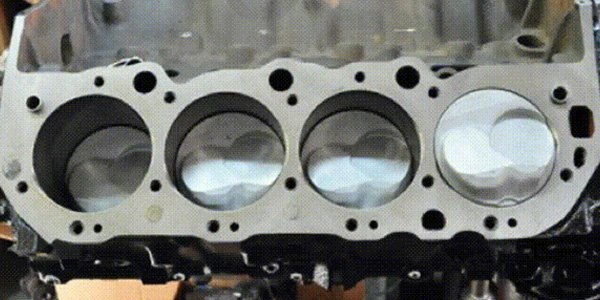
- On the left is the bare casting and on the right is the casting with a Fel-Pro head gasket installed on a Big Block Chevy Engine. The coolant holes in the block casting are much larger than those in the Fel-Pro head gasket; this is by design.
CONTROLLING COOLANT HOLES
- Besides the reduction in size of the top coolant holes, the large coolant hole on the bottom right of the superimposed gasket above is partially blocked off. There are also holes in the gasket which are not open in the block. Some Big Block Chevy engines have these holes while others do not. This will depend on the generation, application and the intended use of the block. These are not design flaws or oversights – the size and placement of every hole in the gasket is intentional, and this is true for every Fel-Pro gasket.

WHY FEL-PRO USES SMALLER HOLES OR BLOCKS OFF SOME HOLES
- The holes in head gaskets meter the flow of coolant properly through the heads. In most engines, coolant flows from the water pump at the front of the engine block toward the rear, goes up into the head(s), to the thermostat and finally to the radiator once the thermostat opens before returning back to the water pump.
- An improperly sized or placed hole can create a shortcut which prevents coolant from following the correct path through the engine. If the coolant takes a shortcut because a coolant hole is too large at the front of the engine, the rear cylinders can overheat. If the holes are properly placed, but too large, the coolant can pass through the engine too quickly and fail to absorb enough heat, also resulting in overheating.
- So why are the castings made with holes that are larger than they should be or unneeded for proper coolant flow? Engine blocks and heads are sand-cast, meaning sand forms the mold for the casting. The holes must be large enough, and sometimes extra holes must be added, to allow the sand to be completely cleaned from the casting once it has solidified. On older engines, the holes may not always line up due to core shift – that is, the blocks are not always perfectly cast, so the gasket needs to accommodate the fact that different castings may have slightly different hole positioning.
BOTTOM LINE
- Generally, the coolant metering holes in the Fel-Pro gasket will match the metering holes in the OEM gasket, determined by the engine manufacturer at the time the engine was designed and developed. While the visual differences between the block, cylinder head and gasket holes may seem extreme, you can install Fel-Pro gaskets with confidence because every hole is precisely placed and sized to ensure that coolant flow is properly controlled by the head gasket.
- With this in mind, a Fel-Pro head gasket should never be modified in any way – doing so not only prevents proper coolant flow, but also can affect the gaskets ability to seal, as the specialized coatings can be damaged.


