
Counter Person Tips
- Brakes
- Electronics
- Steering
- Driveline
- Fuel
- Suspension
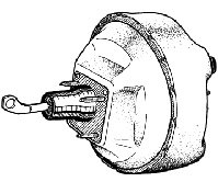
- Counter Tips: Power Brake Boosters
-
Get All the Parts for the Job
- Brake fluid
- Hose clamps
- Tools (vacuum gauge, deep sockets, wrenches, pliers, etc.)
- In-line filters
- Master cylinder
Symptoms of Booster Failure
- Leaking air, venting vacuum
- Vacuum booster noise
- Hard pedal
- Leaking brake fluid
Do the Job Right
- Check brake pedal and master cylinder rod lengths
Carefully match the original and replacement unit rod lengths. Adjust pedal and master cylinder rods, if possible, or reuse the master cylinder rod. If no adjustment or exchange is possible, do not install the replacement unit. All CARDONE loaded brake boosters are preadjusted and ready to be installed.
- Check the vacuum line for gas odor or the presence of moisture
Gasoline or gas fumes can enter the booster through the vacuum line causing internal rubber components to deteriorate which leads to booster failure and voids unit warranty. Check the PCV system and replace or repair system as necessary. Also check the fuel system for rich operation.
- Check in-line vacuum check valves and filters
Be sure all valves operate and replace filters as necessary. Hydrovac systems use an in-line check valve that must be at least 10 inches above carburetor base. Never eliminate loops in vacuum line as these act as moisture and vapor traps.
- Check for sufficient vacuum supply
Use a gauge to measure available vacuum level and volume. For proper operation at least 18 inHg and strong vacuum draw must be available. Low vacuum levels could be caused by loose or defective engine components. Insufficient volume can be caused by a clogged intake manifold vacuum fitting.
- Check outside of master cylinder piston for presence of brake fluid
A defective push rod seal on the original unit has damaged the master cylinder piston seal. Failure to replace a leaking master cylinder will void the booster warranty.
- Follow Cardone’s easy-to-read instructions
Follow the step-by-step, fully-illustrated instructions included with every unit. You should also follow any specific instructions provided by the vehicle manufacturer.
Use Cardone Power Brake Boosters for Long Life and Proven Performance
- Anti-corrosion premium coating
- Bores are fine-tuned, feature O.E. microfinish
- Finest quality rubber components (EPDM classification)
- Bleeder kits and essential hardware included
- Stringent quality control in all stages of manufacturing
- Complete easy-to-follow instructions included
- Counter Tips: Friction Choice Calipers
-
Get All the Parts for the Job
- Master cylinder
- Power brake booster
- Hardware kits
- Specialty tools
- Brake fluid
- Pads
- Hoses/lines
- Rotors/drums
- Combination valve
Symptoms of Caliper Failure
- Pedal vibrates
- Sticking/frozen caliper piston
- Seized bleeder valve
- Erratic braking
- Brakes pull to one side
- Excessive pedal effort
Do the Job Right
- Support vehicle securely
Use a lift or jack stand, never a jack alone.
- Always replace calipers in pairs
- Do not allow caliper to hang by brake line
Use a piece of strong wire to suspend caliper from frame or suspension.
- Do not work on more than one wheel at a time
Work one wheel at a time, using the other as reference.
- Inspect brake pads
Replace if worn beyond specifications.
- Secure pads to caliper
To prevent brake noise, secure pads to caliper, use anti-squeal compound and/or shims.
- Inspect rotors
Resurface or replace if necessary. Use brake cleaner to clean off any grease or oil before caliper is mounted.
- Inspect brake lines
Replace brake lines that are cracked or show signs of softness.
- Flush brake system
The flushing system removes corrosion, dirt and metal particles which can contaminate new calipers and increase possibility of system failure.
- Use approved/new brake fluid
- Use only brake fluid recommended on reservoir lid, owner’s manual, or service manual. Never use petroleum-based fluids or mix fluids.
- Always use new brake fluid from a sealed container. Reusing of old brake fluid will return contaminants and moisture to the system which can cause premature system failure.
- Use approved grease only
Use only high-temperature, silicone-based grease when lubricating slide-type calipers.
- Follow Cardones easy-to-read instructions
Follow the step-by-step, fully-illustrated instructions included with every unit. You should also follow any specific instructions provided by the vehicle manufacturer.
Use Cardone Disc Brake Calipers for Long Life and Proven Performance
- Choose regular premium calipers or loaded premium calipers (with pads)
- O.E. quality seals, boots, and bleeder screws
- Hardware included where applicable
- Meet or exceed O.E. performance
- 100% computer tested before shipment
- Coated to prevent rust and extend life
- Stringent quality control
- Counter Tips: Master Cylinders
-
Get All the Parts for the Job
- Power brake booster
- Calipers (always replace in pairs)
- Tools (flare wrenches, torx-head driver, etc.)
- Brake fluid
- Brake pads
- Hoses/lines
- Hardware kits
- Rotors/drums
- Combination valve
Symptoms of Master Cylinder Failure
- Brakes drag
- Leaking fluid
- Swollen rubber components
- Excessive play in pedal
- Hard pedal
- Decreasing pedal travel
- Pedal sinks to floor
Do the Job Right
- Bench bleed master cylinder before installation
All air must be removed from the master cylinder using the bench bleed method. Failure to do so is the number one cause of failure which may result in spongy or low brake pedal; this will void the warranty. Use bleeder kit supplied.
- Use a wooden dowel or blunt tool
Use only a dowel or blunt tool during bench bleeding. Sharp or metal tools can cause damage to the master cylinder piston and bore.
- Flush entire brake system before installation
Removing all air, dirt and contaminants from the system before installing the master cylinder helps prevent premature brake system failure.
- Use approved/new brake fluid
1. Use only brake fluid recommended on the reservoir lid, owner’s manual, or service manual. Never use petroleum-based fluid or mix fluids.
2. Always use new brake fluid from a sealed container. Reusing old brake fluid will return contaminants and moisture to the system which can cause premature system failure.
- Inspect entire brake system
Inspect the entire brake system before replacing parts. Replace cracked or extremely corroded lines.
- Follow Cardones easy-to-read instructions
Follow the step-by-step, fully-illustrated instructions included with every unit. You should also follow any specific instructions provided by the vehicle manufacturer.
Use Cardone Master Cylinders for Long Life and Proven Performance
- Anti-corrosion coating
- Bores are fine-tuned, feature O.E. microfinish
- Finest quality rubber components (EPDM classification)
- Bleeder kits and essential hardware included
- Stringent quality control in all stages of manufacturing
- Complete easy-to-follow instructions included
How it works and best practices
- Cardone supplies all caliper hardware
-
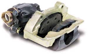
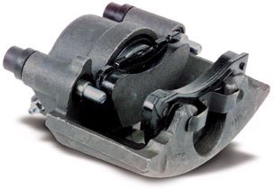
Friction Choice Calipers
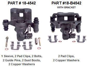
To increase customer satisfaction, Cardone offers Friction Choice Calipers, which include all the hardware needed for installation. This is not limited to Cardone most popular part numbers, but every Friction Choice Caliper is equipped with complete and consistent hardware. The calipers are also available with preinstalled brackets.
The hardware allows for quick and easy installation, because you no longer need to search for replacement components or reuse old hardware. In addition, all rear parking brake hardware is installed and lubricated. Below are examples of A1 Cardone Friction Choice Calipers with their specific hardware. They both fit 1993-2002 Cadillac applications, but one comes with a preinstalled bracket and the other comes without. In either case, all hardware is included to complete the job.
The Cardone dedication to quality and consistency is supported with their focus on facilitating caliper installation and offering you flexibility. With the freedom now available to choose whatever friction is desired, Friction Choice Calipers can be tailored to meet your needs. They offer the winning combination of quality, consistency, and flexibility.
Cardones other caliper offerings include Bolt-on Ready and Severe Duty Friction Calipers.
Bolt-on Ready Calipers
Bolt-on Ready Calipers are equipped with premium-grade pads and all the necessary installation hardware that allows for quick and easy installation.
Severe Duty Friction Calipers
Severe Duty Friction Calipers are bolt-on ready, with extremely endurable pads. These pads are designed for ultimate performance under excessive heat and wear in frequently braking vehicles such as taxis, emergency vehicles and government vehicles.
Every A1 Cardone product must pass various levels of quality control. Cardone’s unprecedented quality management system ensures consistent high quality of every part.
- New and Improved Master Cylinder Bench Bleeding Procedure
-
The most common problem customers face when installing master cylinders is improper bleeding procedures
In the past, Cardone supplied a bleeder kit that consisted of plugs with holes. Tubes pressed on to the holes in order to bench bleed the master cylinder. Although this kit was successful when used properly, it was not the best process. One of Cardones goals in Technical Services is to improve every process.
Cardone found a better way.
The new bleeder kit comes with solid plugs to bench bleed the replacement unit.
The advantages of the new process
- More efficient to bleed the master cylinder.
- No mess or fluid dripping when bench bleeding or when installing the unit on the vehicle.
- Proving the unit is functional during bench bleeding. If the piston is firm when bench bleeding and not on the vehicle when bleeding, the brake system is at fault, not the master cylinder.
The New Process
The following process is supplied with each Cardone replacement master cylinder.
1. Transfer proportioning valves, switches or other components to the replacement master cylinder (as applicable).
2. Tighten bleeder plugs into ports (bleeder plugs may be in a part kit or master cylinder reservoir).
3. Support the master cylinder in a vise in a level position. Never clamp onto the body of the master cylinder.
Note: Units with remote reservoirs should be bled on the vehicle. It is very important that the body of the master cylinder is kept level during the bleeding process.
4. Fill reservoirs halfway or until reservoir ports are covered. Always use new brake fluid from a sealed container as specified by the vehicle manufacturer.
5. Install the reservoir lid so brake fluid does not spray from reservoir during bleeding process.
6. Using a blunt tool or dowel (brake pedal if mounted in the vehicle), slowly press in and release the master cylinder piston using short strokes of 3/4” to 1”. Never stroke piston more than 1”. Repeat this step until resistance to piston movement is firm and less than 1/8”.
Important note: On step-bore master cylinders, wait 20 seconds between strokes. This will allow air trapped in the quick take-up valve to rise into reservoir. Master cylinder body must be level.
7. Install master cylinder on the vehicle. Do not remove bleeder plugs until brake lines are ready to be installed. This prevents air from entering the unit and brake fluid leaking out.
8. Remove one bleeder plug at a time from the master cylinder and connect the proper brake line to that port. Repeat this step for remaining brake line ports. Be sure fluid level is maintained during installation of brake lines and that all fittings are clean before installation. Bleed brake system according to vehicle manufacturer’s procedures and specifications.
9. Verify proper pedal action before moving the vehicle. Do not road test the vehicle until correct pedal feel and travel are obtained.
Note: If firm brake pedal action results using bleeder plugs, but becomes soft after installation in the vehicle, the problem is not the replacement master cylinder.
Installation tip of the month: Read before you proceed!
- A closer look at ABS
-
All anti-lock brake systems are designed to control tire skid and maintain vehicle stability and steering control during panic stopping. By continually monitoring the relative speeds of the wheel assemblies, the processor is able to respond to a skid situation by momentarily reducing the pressure to the brake assembly on the affected wheel(s). By rapidly pulsing the affected brake circuits, the braking load is reduced and allows traction to be regained, thus preventing lock up. Once the need for anti-lock passes, the system returns to normal brake operation.
Basic components consist of wheel speed sensors, electronic control module, hydraulic modulator assembly (which contains electrically operated solenoid valves), pump motor, accumulator and ABS light.
- Wheel speed sensors consist of a magnetic pick-up and a toothed sensor ring. As the wheel assembly rotates, the magnetic pick-up develops an AC (alternating current) signal by making and breaking a magnetic field. The signal is converted into a DC (direct current) signal by the processor, which it uses as a speed indicator.
- The ABS electronic control module is a microprocessor that uses key inputs from the wheel sensors and the brake switch. If the control module detects a difference in the deceleration rate between two or more wheels, it cycles the solenoid valves to regulate hydraulic pressure to the affected brake circuit(s) until the need for ABS control passes and the system returns to normal brake control.
- The hydraulic modulator contains the solenoid valves for each brake circuit. The solenoids in the hydraulic modulator are used to open and close the passages to any given brake circuit to prevent lock up during hard or severe braking.
- The pump motor is used on some applications to provide power assist for normal braking as well as brake pressure for ABS braking. Fluid pumped under pressure is stored in the accumulator and used to provide power assist.
Most ABS failures are caused by contamination, misdiagnosis by the installer, or use of the wrong fluid. The top two complaints about ABS from customers are:
- #1 - pedal pulsation during ABS mode, which is normal.
- #2 - the vehicle does not stop any better than without ABS, this is due to incorrect operation by the driver pumping the brake pedal.
The proper way to use ABS when a panic stop is necessary is to simply press the brake pedal hard until braking is no longer necessary. Pumping the brake pedal will never allow the ABS to control the system.
- Caliper Basics
-
Brake calipers are simple basic components used to apply pressure and stop the rotor from turning which will reduce the vehicle speed. Brake calipers generally house one or two pistons while others can have up to four depending on the application (heavy-duty or performance). Calipers can be bolted in a fixed position or can be a "floating" type. The fixed type implies 2-4 pistons that are bolted to a bracket or the spindle. The pads are configured in such a way that when hydraulic pressure is applied to the pistons, the pads are forced out against the rotor producing the braking action.
The other type of caliper, usually single piston, uses a floating action. With this configuration, the caliper is free to "float" or move on a pair of pins, bolts, or slides. When hydraulic pressure is applied, the piston pushes the inboard pad to the rotor while the outboard pad is pulled against the rotor stopping the disc from rotating.
Calipers consist of a housing, piston(s), seals, dust boot, and a bleeder valve. The pistons can be made of phenolic or steel. The phenolic piston consists of a phenol-formaldahyde resin that is lightweight, heat-resistant, non-corroding, and resists heat transfer.
Most common reasons for failure are:
- Corrosion caused by internal water intrusion (brake fluid absorbs water).
- Sticking or frozen pins, bolts, or slides that cause excessive inboard pad wear.
- Contamination from the brake system.
- Improper fluid when used in a system which uses a petroleum based fluid will cause all rubber components in the brake system to swell.
- Frozen bleeder valves in the caliper housing due to external corrosion.
- Overheating due to residual pressure from the brake system not allowing the piston to return.
- On rear calipers, failure to use the parking brake regularly causes the parking mechanism to corrode and prevents the caliper from being properly adjusted.
Important: Calipers should be replaced in pairs to prevent uneven braking. The brake system should be thoroughly flushed with the recommended fluid from a sealed container and the sliding surfaces must be lubricated with the proper grease for your application.
- What is the Master Cylinder
-
The master cylinder is a foot operated hydraulic pump that sends pressurized brake fluid through the brake lines and into the brake calipers/wheel cylinders.
In its simplest form, the master cylinder consists of a housing, reservoir, piston, rubber cup, return spring and a rubber boot (manual only). A cylinder bore is machined into the center of the housing. The spring, cup and piston(s) slide in this bore and produce hydraulic pressure. The reservoir keeps the system full of fluid as the brake lining wears and the dust boot serves to keep contaminates from entering the rear of the master cylinder.
The dual master cylinder is required on all vehicles manufactured since 1967. Dual master cylinders have two separate chambers that separate the front and rear brake circuits. This type of system prevents the total loss of braking action in the event of brake fluid loss. The brake circuits can be split front and back or diagonally. Both styles will stop the vehicle with only one circuit operating, but it is not safe for normal use.
Operation of the master cylinder is simple. When the brake pedal is depressed, force is applied through the push rod to the master cylinder piston. As the piston cup is forced forward, brake fluid is trapped and hydraulic pressure builds. Hydraulic pressure causes the movement of brake assemblies, such as calipers or wheel cylinders, to stop the rotation of the wheels. When the brake pedal is released, fluid is forced back through the lines into the master cylinder reservoir.
The most common cause of master cylinder failure can be attributed to:
- Contamination - brake fluid is hygroscopic (attracts water)
- Normal wear
- External corrosion
- Mass Airflow Sensors
-
Get All the Parts for the Job
- Test light
- Digital Volt Ohm Meter
- Scan tool
- Wiring diagrams
- Repair manual
Symptoms of ECM Failure
- Erratic idle speeds
- Rough idle/engine surging
- Engine stalling
- Check engine light on
- Loss of power
Do the Job Right
- Obtain trouble codes from computer
Use scan tool or “check engine light” to read codes.
- Check codes to see if MAF sensor is suspect
GM Codes 33, 34, or 36 Ford Code 26, 56, 66, or 76.
- Determine location of MAF sensor
MAF sensors are located in the engine’s air intake duct after the air cleaner.
- Test MAF sensor
With car running, tap MAF sensor. If failure occurs, MAF sensor is defective.
- Test MAF sensor wiring
With vehicle running, wiggle wire harness. If failure occurs, problem is in MAF sensor wiring.
- Remove MAF sensor from car
Check harness and connector for broken wires.
- Remove mounting clamps and O-rings from defective MAF sensor
Clamps and O-rings will be used to install new MAF sensor.
- Check air ducts for damage
For proper operation, there must be no air leaks.
Avoid Warranty Problems
- Use the installation instructions supplied with every MAF sensor
Failure to follow these instructions will void the warranty.
- Make sure all trouble codes are repaired
In addition to the bad MAF sensor, there may also be a defective ECM or other sensors.
- Eliminate engine misfiring or backfiring
An engine backfire will destroy the new MAF sensor.
- Check engine harnesses and connectors for corrosion and damage
Wiggle cables while car is running to see if a fault occurs.
Use Cardone Mass Air Flow Sensors for Long Life and Proven Performance
- The most complete MAF sensor coverage available in the industry
- Every MAF sensor is 100% full function tested
- Tested under simulated extreme temperature, shock, and vibration conditions
- ASE certified technical service available
How it Works and Best Practices
- How Distributors Work
-
Distributors are electro-mechanical devices used to deliver spark to the spark plug at the correct time during the ignition cycle. The distributor can be a contact point type or an electronic type with a pick up coil. The contact point style consists of points, condenser, and a distributor cam on the lobed part of the distributor shaft. The electronic type consists of an electronic module and a pickup coil or hall effect switch.
Point style distributors have lobes on the distributor shaft that open and close the contact points, making and breaking the ignition coil primary circuit.
When the points are closed, a magnetic field builds in the coil. As the points open, the magnetic field collapses sending voltage out of the coil tower through the rotor contacts and down to the spark plugs. Dwell is the amount of time the points remain closed between each point opening. The dwell period is needed to build up a strong magnetic field in the ignition coil to deliver the proper voltage to the plugs. Too much dwell time results in point burning or arcing, too little results in a weak spark. Timing is vacuum and mechanically advanced.
Electronic distributors consist of an electronic control circuit and a magnetic pick up coil or hall effect switch. A trigger wheel located on the end of the distributor shaft replaces the cam lobes used in a contact type distributor. Electronic pulses are produced by the pickup coil or hall effect switch as the distributor rotates and the reluctor wheel passes the pickup assembly. The electronic "switch" located in the ignition module turns the primary coil circuit on and off. Dwell time is regulated in the ignition module under control of the Electronic Control Module. Timing is electronically and mechanically advanced (on some applications).
The main advantage of electronic distributors over contact points style is that there are no mechanical points to wear out or burn, thus affecting the dwell, engine performance and emissions. The electronic distributor is also able to produce a higher spark thus resulting in better performance and reduced emissions levels.
Failure of distributors can be attributed to bushing/shaft wear, worn, frayed, or broken wires, breaker plate wear, lack of lubrication, and/or improper installation of the unit.
- Outsmarting the Smart Cars
-
The ECM’s (engine control computer) function is to control emissions, monitor and regulate engine functions as well as optimize engine performance and fuel consumption. Systems controlled by the ECM include: fuel injection, carburetion, EGR (exhaust gas recirculation), evaporative system, air management, TCC (torque converter clutch) and spark timing.
The computer is constantly updated with data (voltage signals) from the sensors (input) about engine operation. Sensors are variable resistors that modify a voltage to or from the computer. Data is analyzed by the ECM and decision commands (usually ground signals) are sent to control devices (output) based upon inputs from the sensors and ECM preprogrammed memory.
There are 3 types of memory used in ECMs. They are ROM, RAM, and PROM. Read Only Memory (ROM) is a preprogrammed section of memory that can only be read by the computer. If the battery power is lost, ROM memory is not lost, and is retained. Random Access Memory (RAM) contains information that is moved into and out of the RAM and is constantly updated. Sensor information, diagnostic codes and calculation results are stored in the RAM. The loss of battery voltage will result in lost data. Programmable Read Only Memory (PROM) is a factory programmed set of instructions containing the calibration data for the particular vehicles’ engine, transmission, body and axle ratio. This memory may or may not be removable depending upon the vehicle manufacturer. If this memory chip (PROM) is removable, it must be transferred to the replacement unit. If the memory is non-removable, the whole ECM must be replaced.
Failure of emission system components or connections will result in the illumination of the check engine light/SES (service engine soon) light on the dash and a "trouble code" being stored in the memory. Retrieval of the code(s) will identify the problem circuit. This allows the technician to concentrate on the specific circuit affected and perform repairs accordingly. Function tests are then performed to assure the repair is good and the system is functioning properly.
ECMs rarely fail by themselves. Most ECM failures occur due to overloaded circuits caused by shorted solenoids and/or relays (outputs) that do not meet specified OHMS resistance. All ECM controlled components must be checked for proper resistance before the replacement unit is installed or premature failure will result. Bad ground circuits and improper voltages can also lead to erratic operation or damage to the ECM. Voltage supplies should be checked and verified. Grounds should be tested by performing a voltage drop test. To perform a voltage drop test, switch the DVOM (digital volt, ohmmeter) to the low volts or millivolt setting and put the positive lead of the meter to the negative terminal of the battery and the other lead - to the ground circuit at the ECM. The voltage reading should be less than .5 volts, check with the system under a load while wiggling the wires. Voltage over .5 needs to be repaired.
Defects in original equipment ECMs are identified and corrective action taken to upgrade and improve the units. Cardone engine control computer upgrades include: upgraded components installed in critical circuits, installation of heavier injector transistors, circuit protected quad drivers, reflow of solder joints, and an upgraded power supply diode for the ignition circuit (Chrysler) to improve durability.
Of the ECM units returned to the factory as defects, 80% test good, 15% are customer induced failures (shorted solenoids, relays, and burnt components), and 5% are alleged factory defects (check engine light bulb flickers). ECM market replacement percentages are as follows: 69% are GM, 16% are Ford, 13% are Chrysler and 2% are imports.
- Engine Control Computers
-
Todays automotive technology is incredibly powerful. Do you realize a simple greeting card that plays music has more computer power than anything that existed in the entire world before 1950? The average purchaser wears more computing power on their wrists than anything that existed in the entire world before 1961. Todays automobile has more computer brain technology than the first Lunar space module. How Cardone keeps up with this ever-changing technology? Training! Almost everybody has at least one VCR at home. Heres a quick test to see if you are capable of performing automotive electronic repairs. Look at the clock on your VCR. If it flashes 12:00 all day long, you may have trouble performing automotive electronic repairs. But if you can set the time, program the VCR to tape your favorite program and know how to use a remote control, then you can easily fix and repair todays Smart cars.
Let’s look at automotive computers on a simplified level. An ECM (engine control computer) is merely a glorified calculator. The ECM sees numbers from sensors, also known as inputs. It then calculates the information and sends numbers to solenoids, also known as outputs. This process is similar to the human body. When you touch a hot object, nerves (sensors) in your finger send a signal through the nerve cells in your body and into your brain. The brain, like the ECM, makes decisions based on inputs from the nervous system and determines what actions should be taken to correct the situation. The brain then sends a signal to the hand and arm muscles (output) and stimulates the body to move away from the hot object in a relatively short amount of time. It’s a simple process, unless of course, there is a problem.
The ECM monitors and regulates engine functions, emission gasses, as well as optimizes engine performance and fuel consumption. Systems controlled by the ECM include fuel delivery, EGR (exhaust gas recirculation), evaporative system, air management, TCC (torque converter clutch) and spark timing. The ECM is constantly updated with data (voltage signals) from the sensors (input) about engine operation. Sensors are variable resistors that modify a voltage to or from the ECM. Data is analyzed by the ECM and decision commands (usually ground signals) are sent to control devices (output) based upon inputs from the sensors and ECM preprogrammed memory. There are 3 types of memory used in ECMs. They are ROM, RAM, and PROM. Read Only Memory (ROM) is a preprogrammed section of memory that can only be read by the ECM. If the battery power is lost, ROM memory is not lost but is retained. Random Access Memory (RAM) contains information that is moved into and out of the RAM and is constantly updated. Sensor information, diagnostic codes, and calculation results are stored in the RAM. The loss of battery voltage will result in lost data. Programmable Read Only Memory (PROM) is a factory programmed set of instructions containing the calibration data for the particular vehicle’s engine, transmission, body and axle ratio. This memory may or may not be removable depending upon the vehicle manufacturer. If this memory chip (PROM) is removable (GM), it must be transferred to the replacement unit. If the memory is non-removable, the whole ECM must be replaced.
When feedback information affecting the system is out of parameters, the ECM will illuminate the check engine light and a “trouble code” will be stored in the memory. Retrieval of the code(s) will identify the problem circuit or area to be tested. This allows the technician to concentrate on specific circuits affected and perform repairs accordingly. Function tests are then performed to assure the repair is correct and the system is functioning properly.
ECMs rarely fail by themselves. Most ECM failures occur due to overloaded circuits caused by shorted solenoids and/or relays (outputs) that do not meet specified OHMS resistance. All ECM controlled components must be checked for proper resistance before the replacement unit is installed or premature failure will result. Bad ground circuits and improper voltages can also lead to erratic operation or damage to the ECM. Voltage supplies should be checked and verified. A good way to test grounds is through a voltage drop test. To perform a voltage drop test, switch the DVOM (digital volt, ohmmeter) to the low volts or millivolt setting and put the positive lead of the meter to the negative terminal of the battery, and the other lead - to the ground circuit at the ECM. The voltage reading should be less than .5 volts. Check with the system under a load while wiggling the wires. Voltage over .5 needs to be repaired.
Defects in original equipment ECMs are identified to improve ECM durability. Here are some examples of Cardone ECM upgrades: installation of heavier injector drivers, circuit protected quad drivers, upgraded power supply diode for the ignition circuit (Chrysler), re-flow of solder joints and revised conformal coating process (GM). However, even with improvements to the product, the majority of ECMs returned to Cardone as warranties actually test good, or are customer induced failures (shorted solenoids / relays).
How it Works and Best Practices
- Rack and Pinion Units
-
Get All the Parts for the Job
- Outer tie rods
- CTO tie rod installation kit
- Pulley puller (for pump placement)
- Steering coupler
- Specialty tools
- Power steering pump
- Fluid
- Fluid flush
- Magna-Pure filter
- Hoses
Do the Job Right
- Flush the System
1. Flush power steering pump before connecting hoses. When flushing pump, crank engine only (do not start engine).
2. Fill pump reservoir with proper power steering fluid. Crank engine and continue to replenish fluid until fluid coming from hose runs clear. Do not allow pump to run without fluid.
3. If possible, have someone turn steering wheel from full left to full right (avoid hitting stops). This helps purge system of dirt and metal particles.
4. Reconnect return hose and fill reservoir to correct level. The system is self-bleeding, and a few turns from left to right should purge all air.
5. Some applications may require vacuum bleeding to purge all air.
6. Proper steering flushing method.
- Ford Note:
Some Ford pumps are difficult to purge. Result is a “growling” type of noise. Verify that all fittings are airtight by loosening slightly and retightening.
- Replace All Hoses
Hoses deteriorate from inside out. Bad hoses can be difficult/impossible to detect from outside inspection, and one rotted hose probably means all are rotted. Even one bad hose can recontaminate the system.
- Check All Components
Any of system components can retain contamination from old unit and contaminate replacement unit.
- Install New Power Steering Filter
Filters increase life of all components by filtering out particles not removed by flushing procedure and particles caused by every day system wear.
- Always Use New Power Steering Fluid
Use only manufacturer-recommended power steering fluid specific to your vehicle.
- Adjust Belt to Correct Tension (if needed)
Refer to manufacturer’s specifications.
- Perform Wheel Alignment
- Follow Cardone’s Easy-to-Read Instructions
Follow the step-by-step, fully-illustrated instructions included with every unit. Also follow any specific instructions provided by vehicle manufacturer.
- Not All Power Steering Fluids Are Created Equal
-
Having trouble with power steering pumps failing prematurely? Not sure why? Cardone might have a simple answer for you — power steering fluid. Read or you might be surprised.
The Elusive Problem
There can be failure in power steering pumps. Through the process of elimination, Cardone’s engineers arrived at a decision to replace the power steering fluid with another brand and the pump ran beautifully. This led to an in-depth investigation on why fluid brand makes such a difference in pump performance.
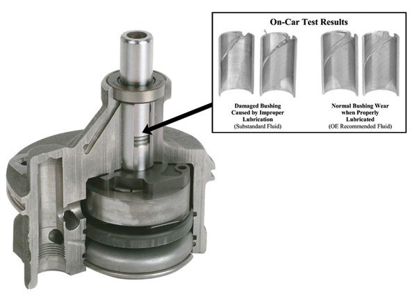
The Testing Process
During extensive lab and on-car testing Cardone engineers learned that there are many substandard power steering fluid brands on the market that lack the additives necessary for proper lubrication of the pump. More specific additives such as viscosity improvers, friction modifiers and anti-foaming agents are not present. Use of a substandard fluid eventually causes the steering system to overheat and the pump bushing to break down. At this point the pump no longer holds pressure which results in a total loss of assist. In fact, during the testing process pump failure due to substandard fluid was recorded in as little as 20-30 minutes after installation!
The Solution
So what power steering fluid should you use? Refer to the vehicle manual or an O.E. vehicle information system (Mitchell’s, Alldata, etc.) to find the recommended fluid for your application. A fluid that meets O.E. standard typically has specific application information printed on the label. A general statement claiming the fluid meets O.E. requirements does not guarantee good fluid quality. Currently there are no API (American Petroleum Institute) standards established for power steering fluid which is why there are so many questionable brands out there. The only standards you can trust today come from the O.E.
The Results
A quality power steering fluid can greatly improve the performance of the steering system. If you are uncertain of your power steering fluid quality, refer to Cardone’s approved fluid list. The fluids listed have undergone independent lab testing to determine their lubricating qualities and additive packages. Not all fluids have been tested yet so check back often to review any updates as additional fluids are tested and found to meet the minimum standards.
- Steering System Flushing Through the Use of the Buddy System
-
The number one steering problem Cardone encounters during analysis of customer returns is failure related to contamination in the system. Failure to flush the system correctly can lead to several premature issues such as binding, poor turnability, leaking, hard steering or noise.
The processes below will greatly minimize steering system contamination while also preventing excessive air from entering the system. During the flushing process, the engine is not running at high RPMs. This does not allow air to enter easily into the system, but bleeding must still be performed.
Use this process to properly flush the steering system when replacing any steering component. Remember that skipping a step in the process usually results in a comeback.
- Fill the power steering pump reservoir with new fluid recommended for your vehicle (or see Cardone’s recommended fluid list), but do not hook up the return hose from the rack and pinion or gear. Place the return hose in a container to catch the fluid and cap the return port on the reservoir to prevent leakage.
- Disconnect the coil in order to allow the engine to crank, but not start.
This is where the buddy system should be used, in order to prevent a run-dry condition and premature damage to the power steering pump. One person needs to crank/turn off the engine, the second person must fill the fluid reservoir and watch the return hose.
Buddy #1: Crank the engine for less than 20 seconds.
Buddy #2: Fill the reservoir
Buddy #1: Turn off the key
- Let the engine rest for about 30 seconds and repeat the flush procedure, as needed until the new fluid runs out of the return hose. Buddy #2 can turn the steering wheel, while cranking, to allow the fluid to pass through all areas of the system.
- Connect the return hoses to the power steering pump.
- Top off fluid reservoir to the specified level.
- Reconnect the coil.
- Continue with the bleeding procedure.
- Start the vehicle and begin bleeding the system of air by cycling the steering wheel from side to side a minimum of four times.
- Take the vehicle for a test drive; if assist is smooth, the bleeding is complete. If assist is erratic and jerky, more bleeding is required.
- Continue bleeding until all air is removed from the system.
- To check a vehicle to see if air is causing a power steering whine, simply take off the cap on the reservoir and inspect the fluid with the engine running. Any foaming or bubbles in the fluid will indicate air in the system that needs to be purged.
Note: Some vehicles require minimal bleeding, while others require patience and persistence. Allowing the vehicle to sit for a few hours may allow the air bubble to rise. If unsuccessful, there may be additional O.E. procedures available.
- Steering System Issues Can Lead to Rack Leaks
-
Before replacing a rack and pinion due to a fluid leak at the input (pinion) shaft seal, always diagnose why. An input shaft seal is not designed to have more than residual pressure. The pressure and flow are retained within the spool valve, unless higher pressure within the system is causing fluid to push beyond the spool valve and into the input shaft sealing area. Its a simple statement, but pressure will always follow the path of least resistance and eventually escape. In this case, please examine the steering system, in order to find and prevent a recurrence.
One potential root cause of residual high pressure can be a restriction in the return line due to rubber breakdown or internal collapse. This causes back pressure to build up in the rack and pinion and an input seal leak. Replacing the return line will eliminate this problem. Also remember that restrictions in the return line can also cause noise, binding, hard steering, leakage and/or poor returnability.
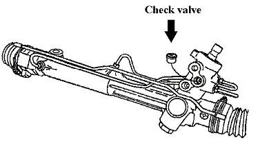
Another root cause of input shaft leaks could be line reversal during installation. Many Ford applications have the same fitting size for both the pressure line and return line, so there is a chance that the pressure line was threaded into the return port and vice versa. If this is done, and the vehicle started, the pressure will be directed through the top of the spool valve and out the input shaft seal. Once this mistake is made, the damage is already done and the unit must be replaced. In order to prevent this, clearly mark the original unit and lines before removing the unit from the vehicle. Use tags or differently colored paint pens, then transfer the tags or markings onto the replacement unit. The same application requires a check valve to be reinstalled in the pressure port of the replacement unit. So don’t send it back with the core. (See figure below).
A common mistake when a leak occurs is to tighten the lines. However, over-tightening will actually compound the problem by stripping the threads. Since most rack housings are made of aluminum, the soft housing threads will strip away against the steel threads of a fitting. Cardone supplies new O-rings or Teflon rings with each unit, in order to provide new sealing materials versus using the old and distressed ones. So take the first step to avoid leaks, and always replace the O-rings or Teflon rings. Last, never use Teflon tape as an attempt to seal the fittings. Teflon has a tendency to cover the ports or unwind into the rack spool valve, causing the unit to fail.
- Twisted Boots Checking the Rack and Pinion
-
Twisted boots on rack and pinion systems are an avoidable comeback failure. To keep this from happening, the following steps should be taken.
After proper installation of a rack and pinion unit, including flushing and bleeding, the vehicle is then sent for an alignment. In order to set the correct toe adjustment, the inner tie rod(s) on the rack and pinion typically must be turned, and this is when the problem starts.
If the boot clamps are not loosened, the tie rods are unable to turn freely inside the boots (bellows), and the boots will become twisted. Once twisted, they no longer move freely with the rack preventing them from expanding and contracting. The boots continue to twist tighter while the vehicle is driven, eventually causing the boots to tear. Water and road debris are then able to enter the rack causing internal rust and damage of the rack shaft seal leading to a leak and premature failure.
A rack and pinion, once completely sealed and operating perfectly, are now defective and the vehicle comes back for an avoidable replacement. Therefore, always check the rack and pinion after the vehicle is returned from alignment to make sure the boots are not twisted.
- Understanding Variable-Effort Steering Systems
-
EVO Steering
Electronically variable orifice (EVO) steering varies the amount of power steering assist based on electrical inputs to provide the driver with improved road feel at higher speeds, and at the same time providing power assist at lower speeds and during parking maneuvers.
EVO systems utilize information such as vehicle speed, steering wheel position, and steering wheel turn rate to calculate and deliver optimum assist to match road conditions.
The EVO system uses a solenoid valve attached directly to the PS system pump’s output fitting or the rack and pinion housing. It is electrically controlled by a digital control signal using pulse width modulation (PWM). By varying the amount of "on-time" or duty cycle of the control signal to the solenoid, variable levels of fluid flow and resulting effort levels can be obtained.
Depending on the year and model, the solenoid could be directed by various control modules. A "dedicated" EVO module was used in the earliest versions of this system. Since that time, however, the electronic-brake and traction-control module (EBTCM) have taken over the responsibilities of VES in most GM products.
Vehicle weight, steering design and suspension geometry vary greatly from platform to platform. Seemingly identical vehicles, with different tire or handling/suspension options, may require slightly different VES behavior. The EVO software is altered to provide ideal assist levels at each speed for this wide variety of vehicles, tailoring the vehicle’s handling "feel" to the vehicle and its intended customer’s preferences. Four or five EVO-module part numbers for the exact same year and model of the vehicle are not uncommon.
An enhancement to EVO-VES systems that began to appear in 1992 included a steering-wheel position sensor (SWPS) or handwheel speed sensor (HWSS), depending on the vehicle platform. This sensor has the ability to input steering wheel position, direction and turn velocity data into the EVO controller. Using this data, the EVO control module can quickly react to emergency evasive maneuvers. If the driver were to suddenly swerve or change lanes to steer around an object on the highway, the EVO module would provide an immediate boost in assist levels, maximizing steering control.
MSVA
One of the renditions of GM VES systems is known as magnetic speed variable assist (MSVA) or MagnaSteer. MSVA was designed specifically to minimize one of the few negative aspects of EVO type steering systems. EVO systems, at highway speeds, restrict the flow from the power steering pump. This restriction raises internal pump pressures as well as the pump’s belt load on the engine. This additional engine load will have a negative impact on fuel consumption and will increase exhaust emissions as well.
The first GM MVSA system, dubbed MagnaSteer, was initially used in 1995 on the G-body platform, the Olds Aurora and Buick Riviera. Cadillac also enveloped this MVSA system into their Integrated Chassis Control System in 1996. MVSA became even more popular with its release in GM’s 1997/98 versions of the Pontiac Grand Prix, Olds Intrigue, and Buick Regal W-body platform.
While the EVO-VES systems were a "bolt-on" addition to an existing power-steering system, MSVA requires a specially designed rack and pinion assembly. An electromagnetic coil within the steering rack’s spool valve has the ability to alter the assist/effort levels by varying the strength and direction of a magnetic field.
To simplify the process, the MVSA module directs the current flow to the electromagnet coil in one direction to increase the amount of assist. Reversing the direction of current flow has the opposite effect.
When no current is flowing through the electromagnetic poles, there is a fixed moderate amount of power steering assist, which can lead to trouble. This default (zero coil current) will approximately equate to the amount of power assist at 30-40 km-h.
- Vacuum Bleeding
-
After replacing a rack and pinion or power steering pump, and proper flushing and bleeding processes are performed, air may remain trapped in the system; this is particularly true on Chrysler Minivan and Ford applications. Hydraulic noise, groaning or whining, will plague the installer until the trapped air is purged from the system, and using vacuum is the best and easiest way to pull these small air bubbles out.
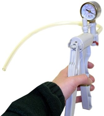
Vacuum Bleeder Tools (Special Service Tools), specific to O.E. applications can be found through Tech Service Bulletins on Alldata or Mitchells. Some models use a reservoir to trap fluid, but this is not necessary to complete the job.
A rubber stopper or plug will be needed to seal off the fill hole of the reservoir. Simply purchase the correctly-sized stopper at your local hardware store. Drill a hole through the center of the stopper and insert the tubing from the vacuum tool into the stopper.
Using the vacuum tool, apply 15 inches Hg. to the pump reservoir with the engine idling. Cycle the wheel from lock to lock every 30 seconds for approximately 5 minutes while maintaining 15” of vacuum. After 5 minutes, shut off the engine and check the fluid level, topping it off as necessary. Repeat these steps until air has been removed from the system and the whining or groaning noise is eliminated.
If air continues to enter the system, you may have a defective pressure hose or connection. It is possible for pressure hoses to allow air to be sucked into the system because of the amount of power steering pressure (some applications as high as 2,000 PSI) but not have external leakage. When in doubt, always change hoses. It is impossible to inspect the internal condition of hoses, so be safe and replace if suspected or if the vehicle has high mileage.
- Understanding the Uniqueness of Center-Take-Off Installation
-
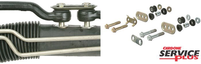
1993 - 2004 Chrysler Group and 1982-1993 General Motors J, L & N body vehicles came equipped with center-take-off (CTO) style rack and pinions. (See Figure 2) These applications are unique in the way the tie-rods are secured to the unit. During replacement, don’t forget to reuse the washers, bolts and lock plate. Pay extra attention to the washers, as years of road grime, heat and material breakdown can cause the washers to bond with the boot. If the washers are not used, the bolts will cause extensive damage internally to the housing. If the fasteners listed above, are either lost or damaged, Cardone has completely new CTO installation kits available for both GM and Chrysler applications, part numbers 22K100 and 22K300, respectively.
Failing to use all components could cause noise, binding or damage to the replacement rack and pinion housing resulting in a very costly mistake or even dangerous situation when driving the vehicle. Following the instructions above will prevent you from running into this problem.
- When Clean is Too Clean
-
Brake Cleaner, Carburetor Cleaner and Engine Degreaser
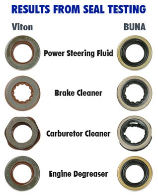
Brake cleaner was specifically mentioned above, but carburetor cleaner and engine degreaser were additionally explored, as all three are common cleaning chemicals.
Rubber components in a steering system are either Viton or BUNA material; therefore seals of both compositions were spray tested with all three chemicals at 100% concentration. Both the brake cleaner and carburetor cleaner samples began to swell 15 minutes after exposure, however, the engine degreaser had no visual change. The seals were then soak-tested for 24 hours in 100% concentration, and further degradation occurred (see picture). The results of the brake cleaner and carburetor cleaner are both undeniable, but the engine degreaser did not cause significant damage to the rubber.
Testing continued with the presumption that the chemicals would not remain at full strength when power steering fluid was added to the system, as in the case where the hoses are sprayed out. Therefore, new seals were soak-tested for 72 hours in a 10% chemical to 90% power steering fluid mixture. Results were not as dramatic as shown in the photo, but the rubber hardness did degrade. In a power steering system, where dynamic function is key during all ranges of heat, flow and pressure, even small changes in the rubber integrity can cause leaking and premature failure.
The Aftermath
The seals seemed to react well against the engine degreaser, but visual appearance is not a viable analysis method, so additional testing will be performed to analyze if any long-term effects occur.
It is understandable that technicians would use brake cleaner and/or carburetor cleaner as a method to clean the system, as both are sold in every parts store across the country, and are known to remove grease and grime better than anything else. However, the attempt to “do some good” can result in the exact opposite.
Therefore, the best advice is to avoid all chemicals completely and simply use the old-fashioned power steering flush method to remove contaminants from the system, as it will avoid introducing foreign elements into the system.
- Remanufactured Drivetrain Products
-

Broad Coverage of Driveshafts and CV Axles
- Full domestic and import coverage from 1966-2016 - 50 years of coverage!
- Domestic and import 4x4 truck and SUV applications.
Remanufactured for Guaranteed Performance
CV Drive Axles
- Shafts are measured for straightness to ensure proper function.
- High-tech grinding machines maintain the original design of the outer housing, race and cage.
- Heat-resistant grease preserves the life of the joint.
- High-quality neoprene boots are tested to ensure durability and longevity.
- Clamps are tightened with pneumatic machinery, creating a perfect seal between the boot and the housing.
- New axle nuts are supplied on all torque-prevailing applications.
- 100% neoprene boots ensure excellent ozone resistance, which eliminates cracking, a leading cause of boot failure.
- Boot clamps are pneumatically crimped creating a perfect seal between the boot and housing.
- High-tech grinding machines maintain the original design of the outer housing, race and cage to guarantee reliable performance.
- Splines are chased 100% to ensure proper fit of axle into the mating hub and transmission, which eliminates installation hassles.
- Threads are chased 100% to ensure proper fit when axle nut is installed.
- Threads and splines are 100% renewed to ensure proper fit the first time.
- Heavy-duty option is available for certain truck and fleet vehicle applications. These applications use thermoplastic boots which have higher spin stability and higher operating temperature compared to the standard neoprene boots and are resistant to impact tears and cracking.
Driveshafts/Prop Shafts
- 100% new universal joints are installed to ensure proper fit and optimal performance.
- All shafts are measured and straightened to ensure like-new performance.
- All slip yokes are lubricated to prevent premature wear and ensure optimal performance.
- Units are 100% dynamically balanced at 3200 RPMs for vibration-free operation and increased joint life. Dynamic balancing is better than static, because the unit is balanced at the typical speed it will experience on the vehicle.
Drive Axle Assemblies
- All bearing pre-loads, axle housings, and shafts are inspected using precision measuring equipment.
- Every unit is tested for drivability by checking the locking mechanism, if applicable, and verifying that there is no gear or bearing noise.
- Housing is powder-coated for maximum corrosion protection that further enhances on-car performance.
- New O.E. ring and pinion gears are inspected for correct backlash and wear patterns.
- Units are remanufactured using O.E. quality bearings, dust shields, seals and gaskets.
- Units come prefilled with oil.

A1 Cardone Advantage
Broadest vehicle coverage - Aftermarket new parts suppliers can only afford to mass produce parts for popular, high-volume vehicles with easy-to-copy designs. That leaves out older vehicles, low-volume models, and late-model, high-tech cars. Even O.E. manufacturers are looking to remanufactured as a solution for today’s vehicle population.
Equal or better quality than new - Through "reverse-engineering" failed parts off the vehicle, Cardone engineers see where and why they failed. They reengineer remanufactured products, where applicable, to reinforce failure-prone areas for longer lasting performance.
Earth-friendly - Cardone restores used auto parts back to their original fit and function, using only about 20% of the energy and raw material needed to build a new part. When you buy remanufactured products, you not only save money, you help save our planet.
- New CV Drive Axles
-

Features and Benefits
- 100% neoprene boots are designed with additional bellows to resist bellow stress and ozone cracking, the leading cause of boot failure.
- A new axle nut is supplied with every unit for hassle-free installation, as the old nut on the vehicle is typically worn or stripped.
- Axle is measured 100% after assembly to ensure proper fit.
- Boot clamps are pneumatically crimped creating a perfect seal between the boot and housing.
- CARDONE Select Engineered (CSE) Technology ensures that all CV axles meet or exceed O.E. form, fit and function.
- High-quality grease withstands high-temperature and high-torque demands to ensure long-lasting, reliable performance.
- Splines are precision rolled to ensure proper fit of axle into the mating hub and transmission, which eliminates installation hassles.
- Threads are precision rolled to ensure proper fit when axle nut is installed.
- Transmission seal diameter is precision-machined after heat treatment to ensure correct surface finish, promoting long seal life.
Cardone Select Advantage
Based on over 46 years of making top-rated remanufactured products, we’ve seen where and why original parts fail. This unique, reverse-engineering expertise is the foundation of Cardone Select Engineered (CSE) Technology. The CSE process identifies and corrects original design flaws, resulting in premium-quality, brand-new parts you can rely on.
Diesel Fuel Injectors
Fleet customers have provided good feedback, commenting that Cardone diesel fuel injectors and turbos have outperformed other brands previously used.
- All gaskets, O-rings and bearings are replaced 100% to ensure optimal performance.
- All products are completely disassembled, thoroughly cleaned and inspected. All components are renewed or replaced as necessary to ensure high quality and durability.
- Each assembled unit is individually calibrated and tested to ensure it meets or exceeds OE form, fit and function.
- When applicable improvements based on typical failure modes of original units are incorporated into the design and manufacturing of replacement component parts, this results into longer service life, less cost and less downtime for the driver.
Diesel High Pressure Oil Pumps
Cardone’s reliable diesel high pressure oil pumps are built and tested to match OE performance. All standard wear parts are replaced and each unit is computer tested to ensure consistent quality.
- All units are built and 100% tested to perform like the original, with all standard wear products replaced.
- Units are remanufactured in a TS 16949 certified facility, which ensures consistent quality.
Diesel Injection Pumps
Cardones reliable light to medium-duty diesel fuel injection pumps are built and tested to match OE performance. All standard wear parts are replaced and each unit is computer tested to ensure consistent quality.
- All gaskets, O-rings and bearings are replaced 100% to ensure optimal performance.
- All products are completely disassembled, thoroughly cleaned and inspected. All components are renewed or replaced as necessary to ensure high quality and durability.
- Each assembled unit is individually calibrated and tested to ensure it meets or exceeds OE form, fit and function.
- When applicable, improvements based on typical failure modes of original units are incorporated into the design and manufacturing of replacement component parts, this results into longer service life, less cost and less downtime for the driver.
Diesel Injection Pumps
Advanced exhaust systems on diesel vehicles play an integral role in reducing emissions to an environmentally friendly level. Diesel particulate filters are responsible for removing soot from the exhaust stream. Historically, when a DPF failed, the only option was to purchase an expensive, brand new unit.
- After reassembly, units are media blasted and coated to renew exterior appearance and increase corrosion protection.
- All applicable OE-quality temperature sensors and sealing gaskets are provided to ensure a complete repair.
- Each unit is flow tested to on-car exhaust levels before and after the remanufacturing process to verify it meets OE performance specs.
- Exhaust hangers and sensor mount holes are welded, where necessary, to return each part to factory fit and function.
- Parts are thoroughly cleaned to remove loose particulate matter and baked at high temperatures to reach required performance levels.
Injector Driver Modules
All electronic modules are 100% computer tested to ensure full functionality. On-car vehicle validation testing ensures that Cardones electronic products meet all product fit, finish, functionality and durability requirements.
- 100% resolder of critical components ensures superior electrical connections, no intermittent failures and longer product life.
- All modules are 100% tested with automated computerized test equipment to ensure functionality and reliability.
- Cardone engineers have identified common wear components that are 100% replaced in Cardones remanufactured units to ensure reliable performance.
- On-car vehicle validation routines ensure that modules meet all form, fit, durability and performance requirements.
Injection Pressure Regulator (IPR) Valves
Cardones reliable injection pressure regulator (IPR) valves are built and tested to match OE performance. All standard wear parts are replaced and each unit is computer tested to ensure consistent quality.
- Remanufactured injector pressure regulator valves are built and 100% tested to perform like the original, with all standard wear parts replaced.
- Units are remanufactured in a TS 16949 certified facility, which ensures consistent quality.
CARDONE = High Quality
Modern air suspension systems rely on air compressors, struts and springs all working in harmony to balance the vehicle and absorb shocks. When everything is functioning properly, the systems works well. However, repairs can be expensive when a component fails. CARDONEs suspension products are a cost-effective alternative that keeps your car running strong.
- Air Suspension Compressors
-
Reliable, Consistant Performance
CARDONE® Remanufactured Air Suspension Compressors are engineered to meet or exceed O.E. performance, but at a fraction of the cost. Original designs are scrutinized for potential improvement and, where applicable, design upgrades are implemented to produce a more durable part than the original. As a direct fit component, ease of installation is guaranteed. Each unit undergoes extensive performance testing to ensure reliable, consistent performance.
- Air Suspension Compressor Dryers
-
Dependability You Can Trust
CARDONE® New Air Suspension Compressor Dryers are grounded in the same reverse engineering competencies that have made Cardone remanufactured products synonymous with quality. Every unit is designed to match O.E. fit, function and performance. With 100% computerized testing, CARDONE New Air Suspension Compressor Dryers provide reliable performance you can trust.
- Air Suspension Springs
-
With CARDONE You Won't Be Stranded
CARDONE® NEW Air Suspension Springs cover the most failure-prone applications on the road at a cost that wont leave you stranded. Building on decades of experience using reverse engineering to remanufacture automotive products, Cardone engineers have meticulously designed and tested air suspension springs to match O.E. performance. Plus, extensive rubber and performance tests ensure these units are strong enough to withstand harsh temperatures and road conditions facing drivers today.
- Air Suspension Struts
-
A Smooth Ride & Keeping Your Car Healthy
A properly operating suspension not only provides a comfortable ride, but is also integral to the overall health of a vehicle’s undercarriage components. Supplied with new shocks, bump stops, rings and high grade seals, CARDONE Remanufactured Air Suspension Struts are engineered to return the suspension to O.E. performance, but at a fraction of the cost. Original designs are scrutinized for potential improvement and, where applicable, design upgrades are implemented to produce a more durable product than the original. As a direct fit component, ease of installation is guaranteed. Each unit undergoes extensive performance testing to ensure reliable, consistent performance.
- Air Suspension Valve Blocks
-
Performance You Can Trust
CARDONE® New Air Suspension Valve Blocks are grounded in the same reverse engineering competencies that have made Cardone remanufactured products synonymous with quality. Every unit is designed to match O.E. fit, function and performance. With 100% computerized testing, CARDONE New Air Suspension Valve Blocks provide reliable performance you can trust
- Shock Absorbers
-
Meticulously Designed and Tested
A properly operating shock absorber not only provides a comfortable ride, but it’s also an integral part of controlling the overall movement of the vehicle’s body during various driving maneuvers. Building on decades of experience using reverse engineering to remanufacture automotive products, CARDONE engineers have meticulously designed and tested Cardone New Shock Absorbers to match O.E. performance. Original units are scrutinized for potential improvement and, where applicable, design upgrades are implemented to produce a more durable product than the original. As a direct-fit component, ease of installation is guaranteed.
- Shock Mounts
-
O.E. Fit, Function, and Performance
CARDONE® New Air Suspension Shock Mounts are grounded in the same reverse engineering competencies that have made Cardone remanufactured products synonymous with quality. Every unit is designed to match O.E. fit, function and performance. With 100% computerized testing, CARDONE New Air Suspension Shock Mounts provide reliable performance you can trust.
- Solenoids
-
Reliable Performance You Can Trust
CARDONE® New Air Suspension Solenoids are grounded in the same reverse engineering competencies that have made Cardone remanufactured products synonymous with quality. Every unit is designed to match O.E. fit, function and performance. With 100% computerized testing, CARDONE New Air Suspension Solenoids provide reliable performance you can trust.