
Information
- Driveshafts 101
- Driveshaft Measurement
- Angle Calibration
- Balancing Service
-
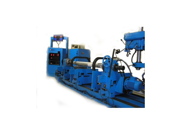
The Driveshaft Shop is proud to now offer actual high speed balancing service. Over the years it has been faced with the question that almost every balancing machine available raises. " How fast is a shaft balanced at? "Most balancing machines are very efficient in doing the job that they are designed for, as long as they are calibrated and working properly. Instead of actual shaft speed, they rely on sensors that detect the "weight centerline" of the part being spun. This means that when the shaft is spinning, the machine is seeing how far out of center the weight is and then goes on to indicate what amount of weight is needed to bring it within a certain tolerance. But not every driveshaft application is the same, and depending on what the driveshaft is going to be used for, some will need to have a more detailed approach in balancing.
That being said, when the shaft is being spun at the actual speed that it will be running at, it presents more information to assimilate and therefore gives the ability to more accurately correct it. Another major advantage is that a high speed balancer will also be able to analyze That being said, when the shaft is being spun at the actual speed that it will be running at, it presents more information to assimilate and therefore gives the ability to more accurately correct it. Another major advantage is that a high speed balancer will also be able to analyze parameters that the slow speed machine cannot, such as u-joint tolerances, tube flex, harmonic resonance, slip yoke instability and more. With this new machine the company can spin a 17lb shaft to actual speeds of over 9000 RPM, whereas most drive shaft balancers only spin from 400-3000 RPM (most average about 1000 RPM). This machine was custom made for The Driveshaft Shop and high speed balancing is offered as a separate service, only from The Driveshaft Shop. parameters that the slow speed machine cannot, such as u-joint tolerance, tube flex, harmonic resonance, slip yoke instability and more. With this new machine we can spin a 17lb shaft to actual speeds of over 9000 RPM, whereas most drive shaft balancers only spin from 400-3000 RPM (most average about 1000 RPM). This machine was custom made for us and high speed balancing is offered as a separate service, only from The Drive Shaft Shop.

- Drag Racing Driveshafts and Street Shafts
-
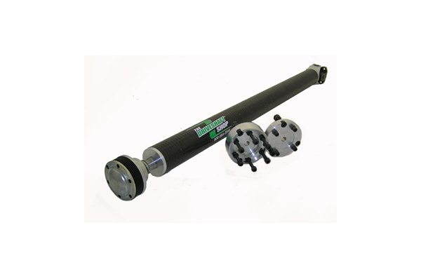
When a company has been around for 30+ years things are into a certain perspective. Either you get old with the rest of the pack or you grow and learn on a constant basis. The Driveshaft Shop grows and learns everyday. Being involved in the racing industry since the early 70’s, The Driveshaft Shop remembers the days on Long Island when Motion Performance was a local shop that just happened to be in Baldwin. Drag racers stopped by on a regular basis (and there still here) and National Speedway was the place to go, those were simpler times. The Driveshaft Shop understands cars and the unique challenges involved in making a racing shaft today. Back in the 70’s it was simple; just use a truck tube and some good joints and you have a race shaft. Technology has changed and so has The Driveshaft Shop. With today’s higher hp/torque motors, higher rpm drive trains and sophisticated suspensions you need to know what you’re doing to make a shaft today. The Driveshaft Shop manufactures driveshafts in standard carbon steel, chromoly, carbon fiber or 6061-T6 aluminum. All of its carbon steel and chromoly shafts are welded to its demanding specs using its unique slow feed lathe mounted welders using a special powdered core wire that has a higher tensile strength than conventional welding. Every shaft is balanced on its state-of-the-art computerized two-plane balancers and weights are attached with its special rivet type mounts. All this is great. But before any shaft is made The Driveshaft Shop carefully makes sure the shaft is designed to specs before it manufactures it, the company could just make a simple flyer to ask what’s needed and it does have that for lower powered cars. The Driveshaft Shop feels at a higher level of competition cars it needs to talk to you and give you a personal assessment of the car to assure its proper part.
The Driveshaft Shop will need to know the following:
- HP/torque of the motor
- Transmission
- Rear ratio
- Rear tire size and height
- Top mph the car will see
- Weight of the car with a driver
With this info The Driveshaft Shop will be able to check for overall strength, the critical speed and durability needed. All shafts are hand made in its Carolina facility and carefully packed for shipping within days.
To check for the critical speed, calculate this equation:
Top speed ________ x 336 (a constant) x rear ratio (like 4.10), then divide it by the tire height (28” tall tire).
Here is an example:
The top speed is 160mph x 336 = 53760 x rear ratio of 4.10 = 220416, then divide this number by the tire height, 28”. This car would have top rpm of 7872. Now the shaft being designed will need to be able to so this rpm.
- Street Rod Driveshafts
-
The Driveshaft Shop is a team of street rod people. Everyone in the building is into some sort of car they love and street rods are not foreign to the company. The Driveshaft Shop manufactures shafts from simple carbon steel to chromoly and finish up the line up with 6061-T6 aluminum. These shafts can be made in any style or arrangement. Where The Driveshaft Shop differs from most companies is that it has an understanding of the entire car. Let’s start with a simple problem. John Knuclebuster has installed a 350/750R in his 47 Chevy and has a vibration when stepping on the gas. He has brought the shaft back to the shop he purchased it from several times only to be told the shaft is balanced and guess what, it more than likely is. A friend of Mr. Knuclebuster checks the pinion angle and tells him it’s correct? What was missed was the front and rear angle and has no more than four degrees of operation. Simple, right? Not really. Due to the 700R sitting so high in the tunnel he can’t get it higher to correct the angle. Solution is a C.V. on the front of the shaft (can be made for just about any car). The story is kind of corny but The Driveshaft Shop has been around for years and hears stories like this over and over. Not only can it make the best shaft for the car, but if there is a problem the company will stay with it until the end. Professional drive train people doing what they love, making parts.
- Driveshaft Vibration: 101 (not for CV axles)
-
Most people have trouble determining if the vibration in their vehicle is coming from the driveshaft or not. There are typically two types of vibration most vehicles would have. A fast cycle vibration or a slow cycle vibration, to help understand this lets say you put a bucket of water on the passenger’s floor. If the vibration in the vehicle produces small ripples on the top of the water this would be considered a fast cycle vibration. This type of vibration is usually a drivetrain vibration, things like the driveshaft, motor or torque converter. If the vibration puts waves on the top of the water or splashes, this type of vibration is a slow cycle vibration and usually is an axle or tire vibration. People have trouble determining where the vibration in their vehicle is coming from.
- Jack Test
-
A simple way to do this is out the vehicle in question up on jack stands (make sure the vehicle is completely secure), block the front tires and run the vehicle up to the speed you have the vibration. Make sure you use the brake to stop the drivetrain before you put the car in park if it’s an automatic. If the vibration is a fast cycle vibration you may want to have the driveshaft checked for balance. This may make no sense to you but you may try indexing the shaft 180 degrees (just pull the shaft off the rear yoke and put it on the opposite way). What this does is change the resonant frequency property of the driveline and in many cases it takes the vibration away. If you have a slow cycle vibration take the tires off the car (make sure you put lugs back on the axle to keep the brake in line) and run the vehicle again. If the vibration is gone you now have to find out if it’s the rim or the tire and good tire shop can help you with that. This is a simple test for any vehicle but please if you’re not completely sure of how to put the car on stands safely bring the car to a certified technician to perform the test.
- For vehicles with a Live Rear Axle:
-

Measure from the edge of the seal (not the output shaft) to the centerline of the rear u-joint.
Please do this at ride height. The car can be lifted under the differential but make sure it has the weight on the rear springs
To properly measure the rear end yoke, first determine if the yoke has (2) tabs that the rear joint will sit-in between, or if there are no tabs (tabs are in the picture above) or if it has a flat plate. Be very careful with this measurement. The size changes in increments of 1/16" (1-1/16" | 1-1/8" | 1-3/16")
- For Vehicles with a Slide in Transmission Yoke and a Flat Flange on the Differential:
-

Also measure the flange pattern as shown here:

Measure flange pattern:
- 1 - Center of the bolt hole to center of the bolt hole - vertical
- 2 - Center of the bolt hole to center of the bolt hole - horizontal
- 3 - Centering pilot diameter (can be male OD or female ID - specify)
- For Vehicles that Use a Flat Flange on the Transmission and a Flat Flange on the Differential:
-
Measure from the bolt face of the transmission flange to the bolt face of the differential flange (your factory driveshaft and any couplers must be removed prior to measuring)

Please provide the following information:
- 1. Transmission year/make/model (please advise spline count if possible)
- 2. Differential info: What did it come from? Does it have u-bolts or straps and (4) bolts, or does it have a flat plate (3-bolt / 4-bolt / 6-bolt)?
- 3. What hp and torque does the engine currently produce?
- 4. If the car is being built for competition please provide a full run down of the car, including its weight, tire size and rear gear ratio. All of this will help get you the correct shaft.
One of the most misunderstood things in drivetrain technology is understanding the driveshaft angle and what its effects are on a vehicle. The Driveshaft Shop will try to make this as simple as possible. As a driveshaft turns at a given angle, the joint moves in a forward to back motion. The first spot is the transmission angle and second is the shaft's angle. The movement makes an X on paper if you were to map it out. Quite simply, if the X or angle measurement on the top isn't the same as on the bottom, you will end up with a bicycle crank type movement. In other words, one movement will not counteract the other movement. Most angle vibrations are in the lower mph range (30-45mph) but can be seen higher. If you have a vibration under 15 mph, more than likely, there is something bent under the vehicle.

Please use the above chart to check your driveshaft angle
The picture above shows a simple driveline and how its angles are laid out. This is a text book layout and if you can achieve angles like this, please do. But remember, its not a perfect world and there are different factors to deal with when building a car. With all the vehicles The Driveshaft Shop has been under, it never ceases to amaze it, what should work doesn't and what shouldn't work does. The point the company is trying to make is to get the angles as close as possible. If there is a problem, it can be taken care of at that time. Make sure both top and bottom angles do not exceed 4 degrees. If they do, it will need some sort of C.V. or a double cardan style joint.